Dual-fan hairdrying apparatus

a hair dryer and dual-fan technology, applied in the direction of hair dryers, lighting and heating equipment, machines/engines, etc., can solve the problems of burn injuries or discomfort, hair damage, and practical limits, and achieve the effect of smooth and efficient airflow path and increased air velocity

Inactive Publication Date: 2006-11-16
CONAIR CORP
View PDF18 Cites 37 Cited by
  • Summary
  • Abstract
  • Description
  • Claims
  • Application Information

AI Technical Summary

Benefits of technology

[0007] It is desirable to provide a handheld hair drying appliance that increases air velocity compared to known handheld hair drying appliances while avoiding the shortcomings described above and while achieving other benefits.
[0008] A handheld hairdrying appliance according to a preferred embodiment of the present invention comprises an electric heat element and an electric motor for rotating fan blades from a plurality of in-line fans that move air past the heat element to deliver heated, flowing air from an exit port, in addition to a tube-like sleeve with a smooth, cylindrical inner surface that has an inner diameter that closely fits around the outer diameter of the fan blades, thereby creating a smooth and efficient airflow path.

Problems solved by technology

While increasing each of these factors generally improves hair drying time, there are practical limits.
For instance, if the temperature of the heat is too high it can cause hair to become damaged or it can cause burn injuries or discomfort.
Attempts to increase air velocity include increasing the speed of the fan blade, which typically results in increased noise and a need to upgrade the electric motor to handle increased rotational velocities under load, thereby adding cost and weight.
This counter-effect diminishes the efficiency of the motor and its velocity-generating effect and it diminishes the efficiency of the heating element.
The embodiments disclose interior spaces where the inner walls of the flowpath have irregularities in shape and smoothness, and that have additional physical components interfering with the airflow, thus causing noise and inefficient airflow.

Method used


Image

  • Dual-fan hairdrying apparatus
  • Dual-fan hairdrying apparatus
  • Dual-fan hairdrying apparatus

Examples


Embodiment Construction

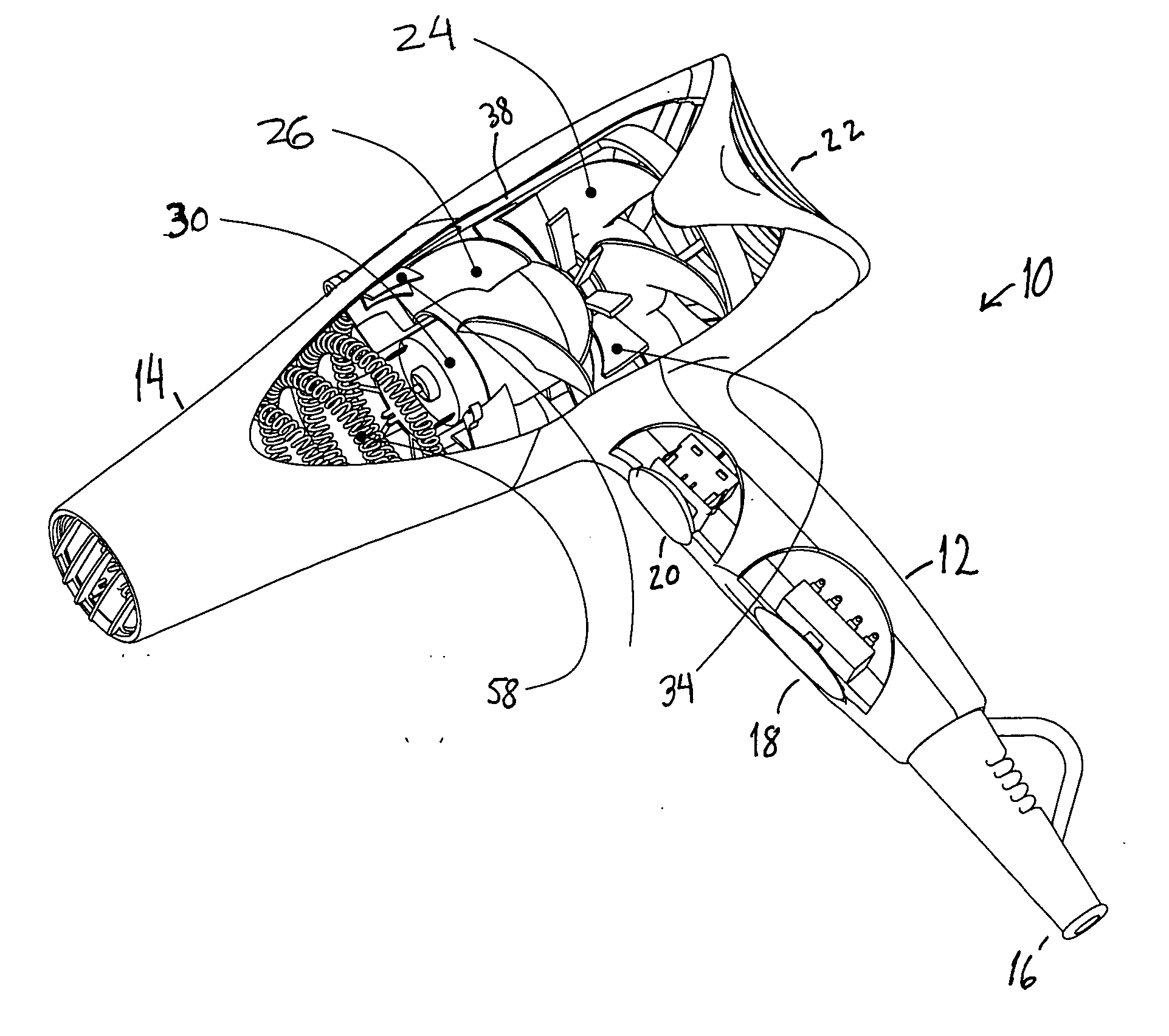
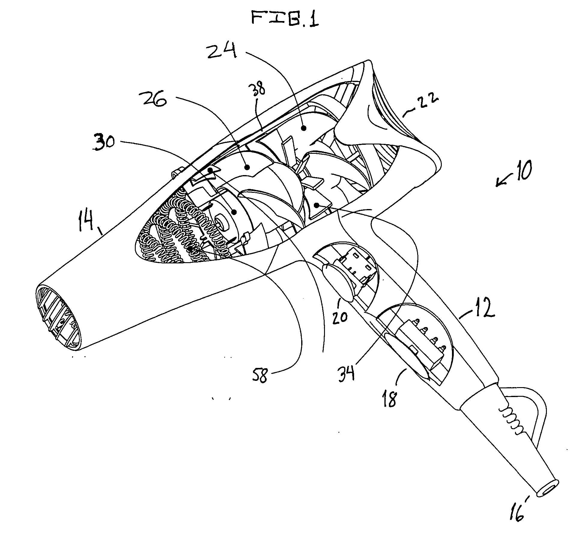
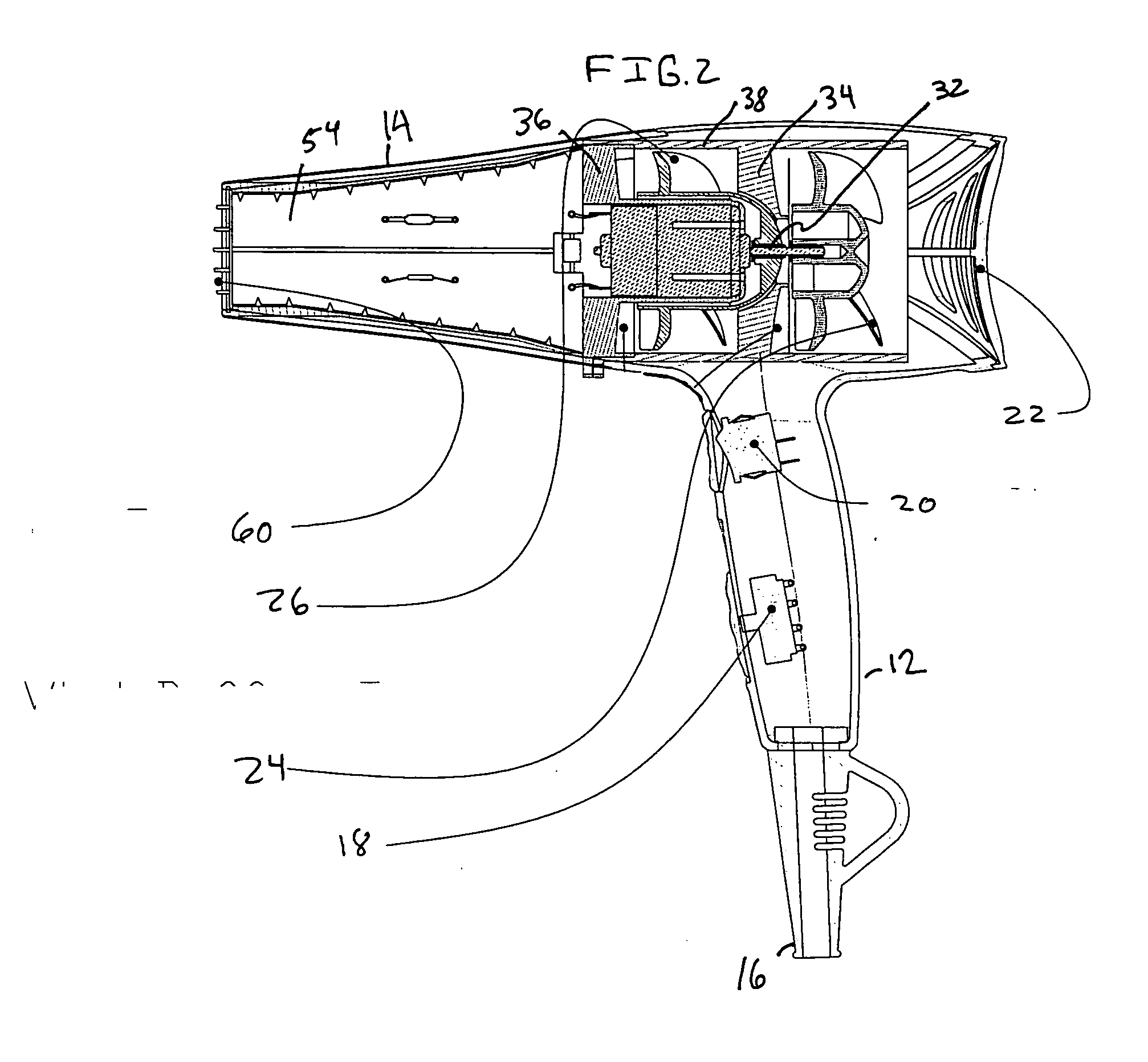
[0013] Referring to FIGS. 1-4, a hair drying appliance (10) comprises a housing having a handle portion (12) and a tube portion (14). The handle (12) includes a power cord (16), an on / off power switch (18), and a “cool-shot” control switch (20). An inlet portion (22) at one end of the tube portion (14) receives incoming airflow which is pulled in by a vacuum effect created by the rotation of a first fan blade (24) and a second fan blade (26), each coaxially aligned to rotate about a common axis. An electric motor (28) is housed in a generally cylindrical motor mount (30) from which a rotating shaft (32) extends for mounting and driving the first blade (24) and the second blade (26). A dome-shaped cap (35) is mounted to the shaft (32) near one end of the motor mount (30) for air-flow efficiency and to support the second fan blade (26). A first set of vanes (34) is mounted adjacent to and downstream of the first blade (24) and a second set of vanes (36) is mounted adjacent to and down...


PUM


Abstract

A handheld hair drying appliance (10) has an inlet portion (22) at one end that receives incoming airflow which is pulled in by a vacuum effect created by the rotation of a first fan blade (24) and a second fan blade (26), each coaxially aligned to rotate about a common axis. A tube-shaped sleeve (38) having a smooth, cylindrical inner surface is mounted inside of a tube portion (14) of the appliance and surrounds the motor and blade assembly such that the blade diameters are slightly smaller than the inner surface of the sleeve (34), but closely fitting, thereby optimizing vacuum pressure and air velocity to produce high output air velocity in an efficient manner.

Description

CROSS-REFERENCE TO RELATED APPLICATIONS [0001] None. BACKGROUND OF THE INVENTION [0002] 1. Field of the Invention [0003] The present invention relates to an apparatus for drying hair and, more particularly, to a handheld hair dryer having an electric motor, a heating element and fan blades. [0004] 2. Description of Related Art [0005] Known handheld hairdrying appliances typically include an electric heat element and an electric motor for rotating fan blades that move air past the heat element to deliver heated, flowing air from an exit port. Various factors that affect the performance in terms of how quickly hair is dried include heat temperature, airflow rate, and air velocity. While increasing each of these factors generally improves hair drying time, there are practical limits. For instance, if the temperature of the heat is too high it can cause hair to become damaged or it can cause burn injuries or discomfort. Airflow rate is limited by cross-sectional area of the flowpath and...

Claims


Application Information

Patent Timeline
Patent Type & Authority Applications(United States)
IPC IPC(8): F26B3/02F26B21/04
CPCA45D20/10F04D19/007
Inventor ZHEN, TIM TAO
Owner CONAIR CORP
Why Eureka
Try Eureka