
Office accessory

Inactive Publication Date: 2006-11-16
LOIBL BERND
View PDF12 Cites 9 Cited by
  • Summary
  • Abstract
  • Description
  • Claims
  • Application Information

AI Technical Summary

Benefits of technology

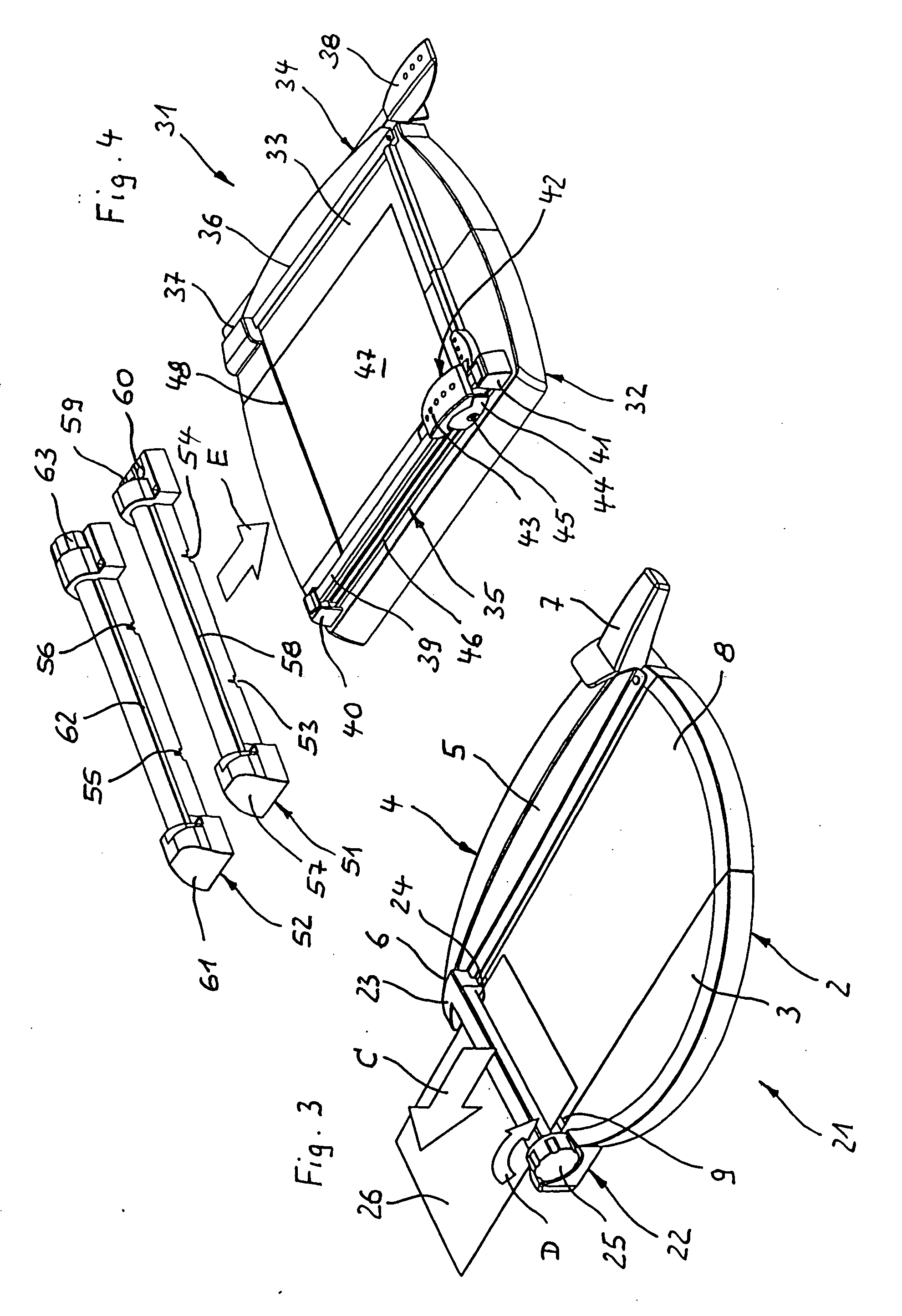
[0009] According to the present invention, this object is achieved in that the office accessory comprises, in addition to the at least one cutting device, at least one laminating device for laminating sheet material to at least one film. The basic idea of the invention is therefore to combine two (or more) devices, having different functions, into one combined office accessory. This combination yields considerable advantages. For example, the space requirement of the office accessory according to the present invention is substantially smaller. Advantages in handling also result from the adjacent arrangement of the cutting device and laminating device. The trimming of a sheet in order to prepare for a subsequent laminating operation can be performed with no change in location, which is practical and saves time.
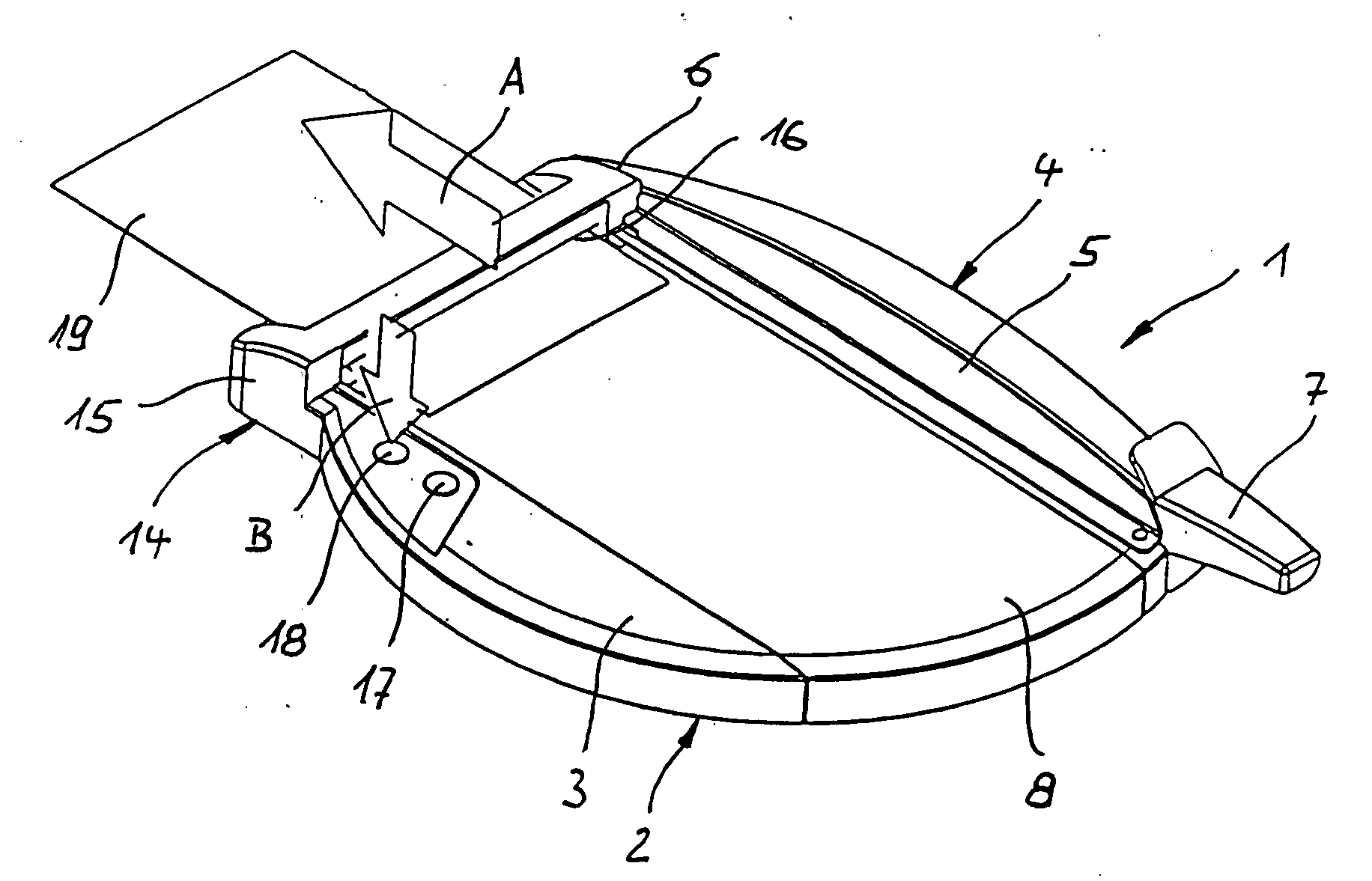
[0010] In an embodiment of the invention, provision is made for the laminating device to be arranged or attachable on one side of the support plate, its insertion opening for the introduction of sheet material and film(s) preferably facing toward the support plate, in particular in such a way that the lower side of the insertion opening is flush with the upper side of the support plate. The support plate thus assumes a dual function, since it can perform its supporting function both during the cutting operation and upon insertion of the combination of sheet material and film. This results in a particularly small space requirement.
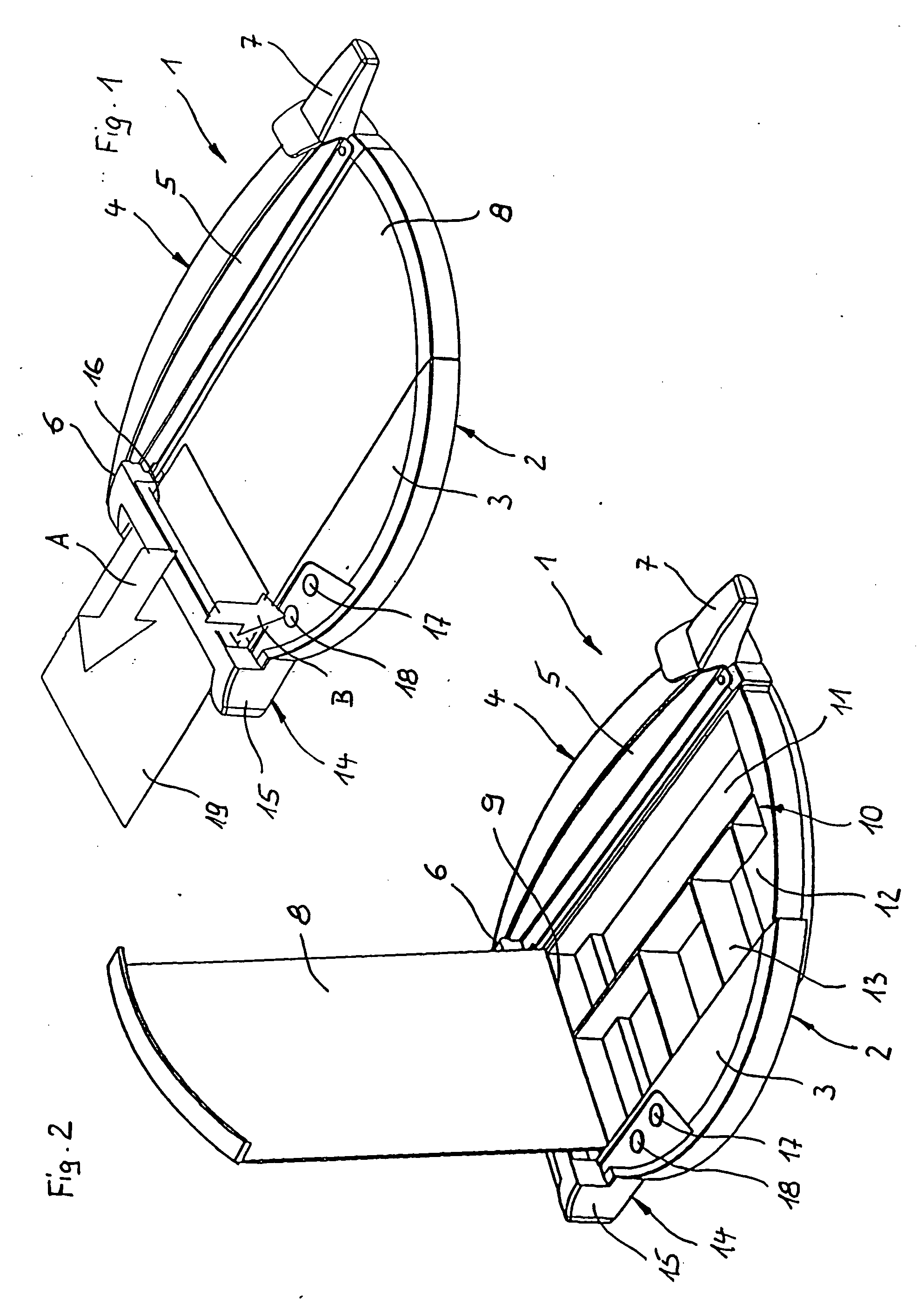
[0016] Provision is further made, according to the invention, for at least one storage compartment to be provided beneath the support plate, preferably at a horizontal spacing from the at least one cutting device. This creates the possibility of using, as a storage compartment, the space beneath the support plate hitherto unused in cutting units. Office accessories such as staple removers, staplers, or the like, but also other office items such as staples, writing instruments, or sheet materials such as paper or films, can be accommodated in this storage compartment without an additional space requirement. This creates circumstances such that the operations arising before or after a cutting and / or laminating operation can be performed contemporaneously and without delay, and the space around the office accessory remains clear for actual office work.

Problems solved by technology

Advantages in handling also result from the adjacent arrangement of the cutting device and laminating device.
This results in a particularly small space requirement.

Method used


Image

  • Office accessory
  • Office accessory
  • Office accessory

Examples


Embodiment Construction

)

[0027] Office accessory 1 depicted in FIGS. 1 and 2 comprises a frame plate 2 whose horizontal upper side forms a support plate 3 for the placement of sheet material. A guillotine cutting device 4 is located on the upper side of frame plate 2.

[0028] Guillotine cutting device 4 comprises a knife arm 5 that is mounted pivotably, in a bearing 6, about a horizontal axis extending transversely to the longitudinal side there. Knife arm 5 is equipped on its lower side, substantially over its entire length, with a cutting knife that is concealed in this view. Configured at the free end of knife arm 5 is a handle 7 with which knife arm 5 can be pivoted upward and downward about bearing 6. In the position shown, knife arm 5 is located in the lower terminal position.

[0029] The larger portion of support plate 3 is separated from the remaining portion, and forms a cover plate 8. It is mounted upwardly pivotably on one side via a hinge 9, about an axis that extends parallel to the axis of bear...


PUM

PropertyMeasurementUnit
Fractionaaaaaaaaaa
Areaaaaaaaaaaa
Transparencyaaaaaaaaaa

Abstract

An office accessory for processing sheet material such as paper and / or films has a support plate to support the sheet material during the processing operation. At least one cutting device is associated with the support plate. The office accessory additionally comprises at least one laminating device for laminating sheet material to at least one film.

Description

CROSS-REFERENCE TO RELATED APPLICATIONS AND CLAIM TO PRIORITY [0001] This application is based upon utility model application number 20 2005 007 860.3, filed May 13, 2005 in the Federal Republic of Germany, the disclosure of which is incorporated herein by reference and to which priority is claimed. FIELD OF THE INVENTION [0002] The invention concerns an office accessory for processing sheet material such as paper and / or films, having a support plate to support the sheet material during the processing operation and having at least one cutting device associated with the support plate. BACKGROUND OF THE INVENTION [0003] Office accessories of the aforementioned kind are used for trimming of sheet material such as paper, films, or photographs. In the existing art they are embodied as cutting units only, and comprise a support plate on which the sheet material to be trimmed can be placed for the cutting operation. Arranged at one edge of the support plate is a cutting device, usually in ...

Claims


Application Information

Patent Timeline
IPC IPC(8): B32B38/04
CPCB23D35/008B26D1/185B26D1/30B26D7/00B26D9/00Y10T156/12B32B38/0004B32B39/00B32B2037/0061Y10T156/1317Y10T156/1378B32B37/182
Inventor LOIBL, BERND
Owner LOIBL BERND
Learn More