Longitudinal support

a technology of longitudinal support and supporting elements, applied in the direction of internal osteosynthesis, osteosynthesis devices, constructions, etc., can solve the problems of biocompatibility and high elasticity of materials

Inactive Publication Date: 2006-11-16
DEPUY SYNTHES PROD INC
View PDF21 Cites 47 Cited by
  • Summary
  • Abstract
  • Description
  • Claims
  • Application Information

AI Technical Summary

Benefits of technology

[0018] In yet another embodiment, the fixing means may comprise an elastically expandable clamp that can be placed over the articulated socket and snapped onto the head segment of the bone fixing means. After the assembly of the clamp, the articulated socket is compressed by the clamp. This has the advantage, that due to the compressing of the second articulated part, the

Problems solved by technology

Such a material is biocomp

Method used


Image

  • Longitudinal support
  • Longitudinal support
  • Longitudinal support

Examples


Embodiment Construction

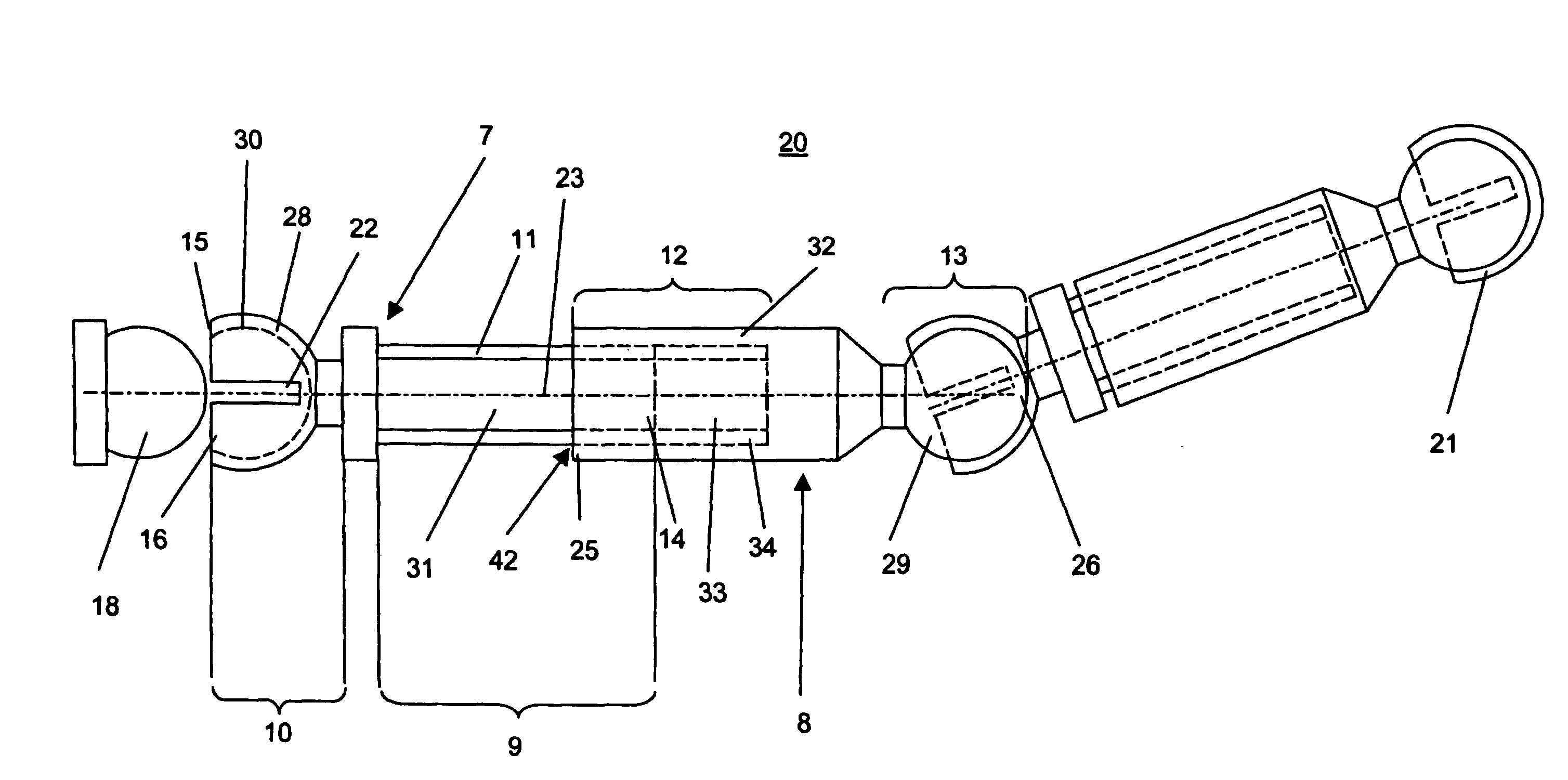
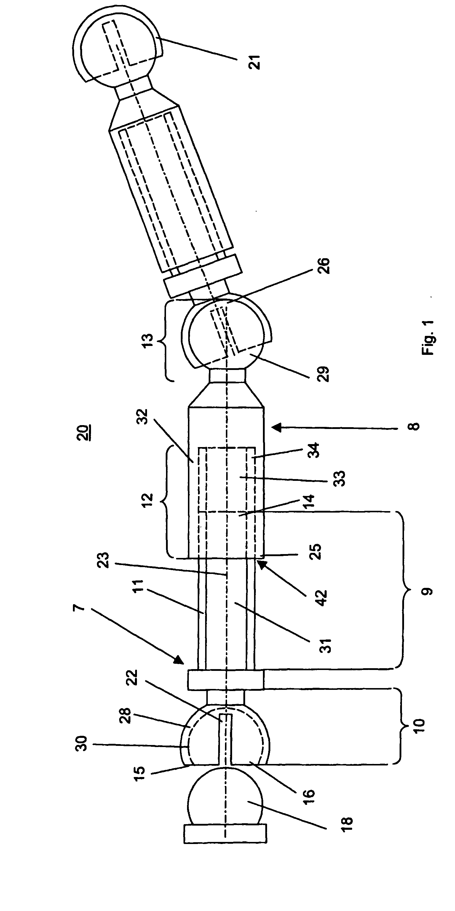
[0024]FIG. 1 illustrates an embodiment of the longitudinal support 20. The longitudinal support 20 has type A longitudinal support elements 7, type B longitudinal support elements 8, and end-pieces 18 and 21.

[0025] Type A longitudinal support element 7 includes first connecting segment 9 and second connecting segment 10 which are coaxial with a first longitudinal axis 23 of the longitudinal support element 7. The longitudinal support element 7 has a first end 14 and a second end 15. The second end 15 is located next to the second connecting segment 10. The first connecting element 9 of the longitudinal support element 7 (type A) is constructed as a cylindrical shaft 31 with a thread 11. The second connecting segment 10 of longitudinal support element 7 (type A) comprises an articulated socket 28 with a hollow spherical segment-like, coaxial cavity 30. The socket 28 can be elastically deformed transversely to the first longitudinal axis 23, while the cavity 30 at the second end 15 o...


PUM


Abstract

A longitudinal support having a first and second longitudinal support element. The first longitudinal support element having a longitudinal axis, includes first and second coaxial connecting segments provided with a first end and a second end, and an deformable articulated socket on the second connecting segment first longitudinal support element. The deformable articulated socket is axially open and can be deformed transversely to the longitudinal axis. The articulated socket includes a hollow spherical segment-like cavity with a diameter of D with an opening on the second end that is concentric with the longitudinal axis and has a diameter of d, while d<D. Further, the first connecting segment of the first longitudinal support element has a thread extending parallel to the longitudinal axis. The second longitudinal support element having a longitudinal axis, includes first and second coaxial connecting segments with a first end and a second end. The first connecting segment is able to be connected with the first connecting segment of the longitudinal support element, and the second connecting segment includes an articulated head that is complementary to the articulated socket.

Description

CROSS REFERENCE TO RELATED APPLICATION [0001] This application is a continuation of International Patent Application No. PCT / CH2003 / 000605, filed Sep. 8, 2003, the entire contents of which is expressly incorporated herein by reference. TECHNICAL FIELD [0002] The present invention relates generally to longitudinal support elements to stabilize bones, particularly bodies of the vertebra. BACKGROUND OF THE INVENTION [0003] The current treatment for damaged or tumorous bodies of the vertebra usually comprises implanting a rigid longitudinal support, anchored on the bodies of the vertebra by bone anchoring means or a rigid bone plate. The purpose of these devices is to prevent, by means of the rigid implants, the movement of the bodies of the vertebra stabilized in this manner relative to one another and to promote the fusion of adjacent bodies of the vertebra. [0004] A device to stabilize the bodies of the vertebra using a multi-segmented longitudinal support that can be fixed in a desi...

Claims


Application Information

Patent Timeline
IPC IPC(8): E02F3/00A61B17/70
CPCA61B17/7005A61B17/7014A61B17/705A61B17/7037A61B17/7032
Inventor HARTMANN, STEPHANSTUDER, ARMIN
Owner DEPUY SYNTHES PROD INC
Why Eureka
Try Eureka