Prosthetic valve that permits retrograde flow

a technology of retrograde flow and prosthesis, applied in the field of medical devices, can solve the problems of loss of effectiveness, physical manifestations and pathologies, and insufficient venous valves, and achieve the effects of preventing pooling of blood, preventing the formation of thrombosis, and increasing the overall acceptance of the device by the hos

Active Publication Date: 2008-07-22
COOK MEDICAL TECH LLC
View PDF30 Cites 77 Cited by
  • Summary
  • Abstract
  • Description
  • Claims
  • Application Information

AI Technical Summary

Benefits of technology

[0012]The device includes at least one leaflet attached to the support structure. The leaflet provides a valve function to the device. In one embodiment, the leaflet provides the valve function by moving between first and second positions while remaining attached to the support frame. In one position, the leaflet substantially blocks the lumen of the vessel, while the lumen is substantially open when the leaflet is in the second position. Thus, the leaflet permits fluid flow through the vessel in a first direction when in the first position, and substantially prevents fluid flow through the vessel in a second, opposite direction when in the second position. The leaflet can be formed of a bioremodellable material, such as small intestine submucosa (SIS) or other extracellular matrix (ECM) material.
[0013]The device includes an opening that permits a controlled amount of fluid flow through the device in the opposite direction when the valve is closed. Thus, while the leaflet substantially prevents fluid flow in the second, opposite direction, the device includes an opening that allows some flow of fluid in this direction. Allowing such flow, retrograde flow, lessens pooling of fluid around the device when the leaflet is in the closed, or second, position. This is expected to prevent pooling of blood around the device, which may prevent formation of thrombus and increase the overall acceptance of the device by a host.

Problems solved by technology

Varying fluid pressures over time, however, can introduce a reverse flow direction in the vessel.
While natural valves may function for an extended time, some may lose effectiveness, which can lead to physical manifestations and pathology.
For example, venous valves are susceptible to becoming insufficient due to one or more of a variety of factors.
Over time, the vessel wall may stretch, affecting the ability of the valve leaflets to close.
Furthermore, the leaflets may become damaged, such as by formation of thrombus and scar tissue, which may also affect the ability of the valve leaflets to close.
Once valves are damaged, venous valve insufficiency may be present, and can lead to discomfort and possibly ulcers in the legs and ankles.
Prior art prosthetic valves, however, do not permit a controlled amount of retrograde flow.

Method used


Image

  • Prosthetic valve that permits retrograde flow
  • Prosthetic valve that permits retrograde flow
  • Prosthetic valve that permits retrograde flow

Examples


first embodiment

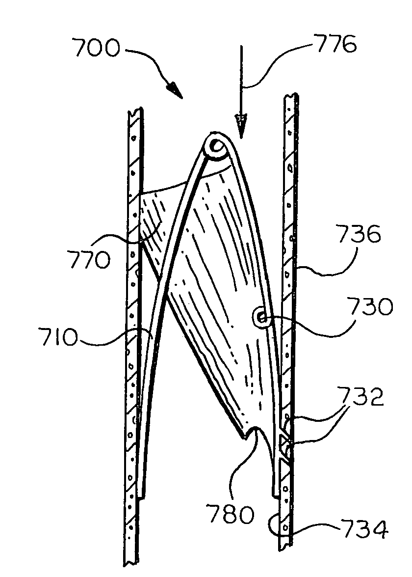
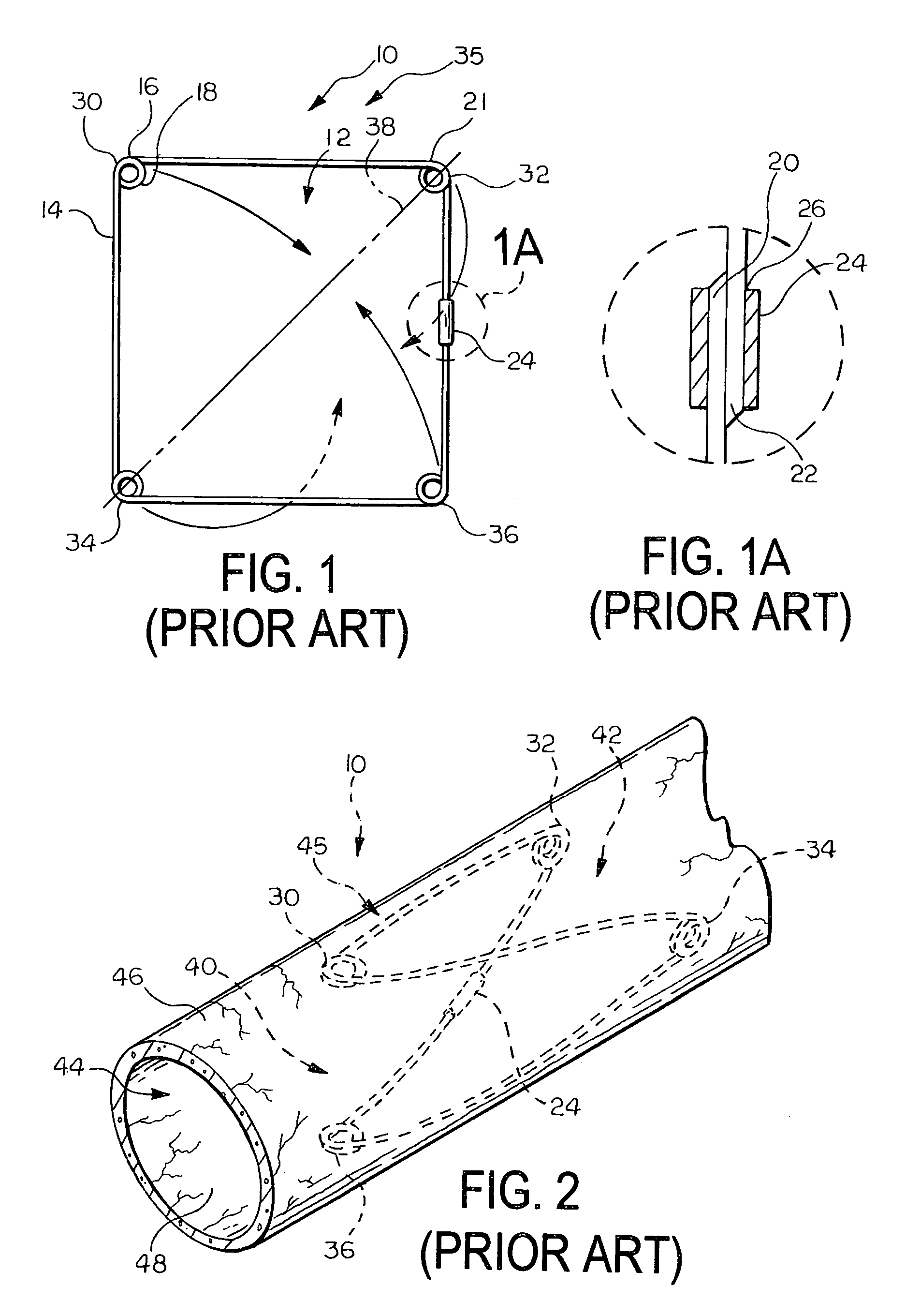
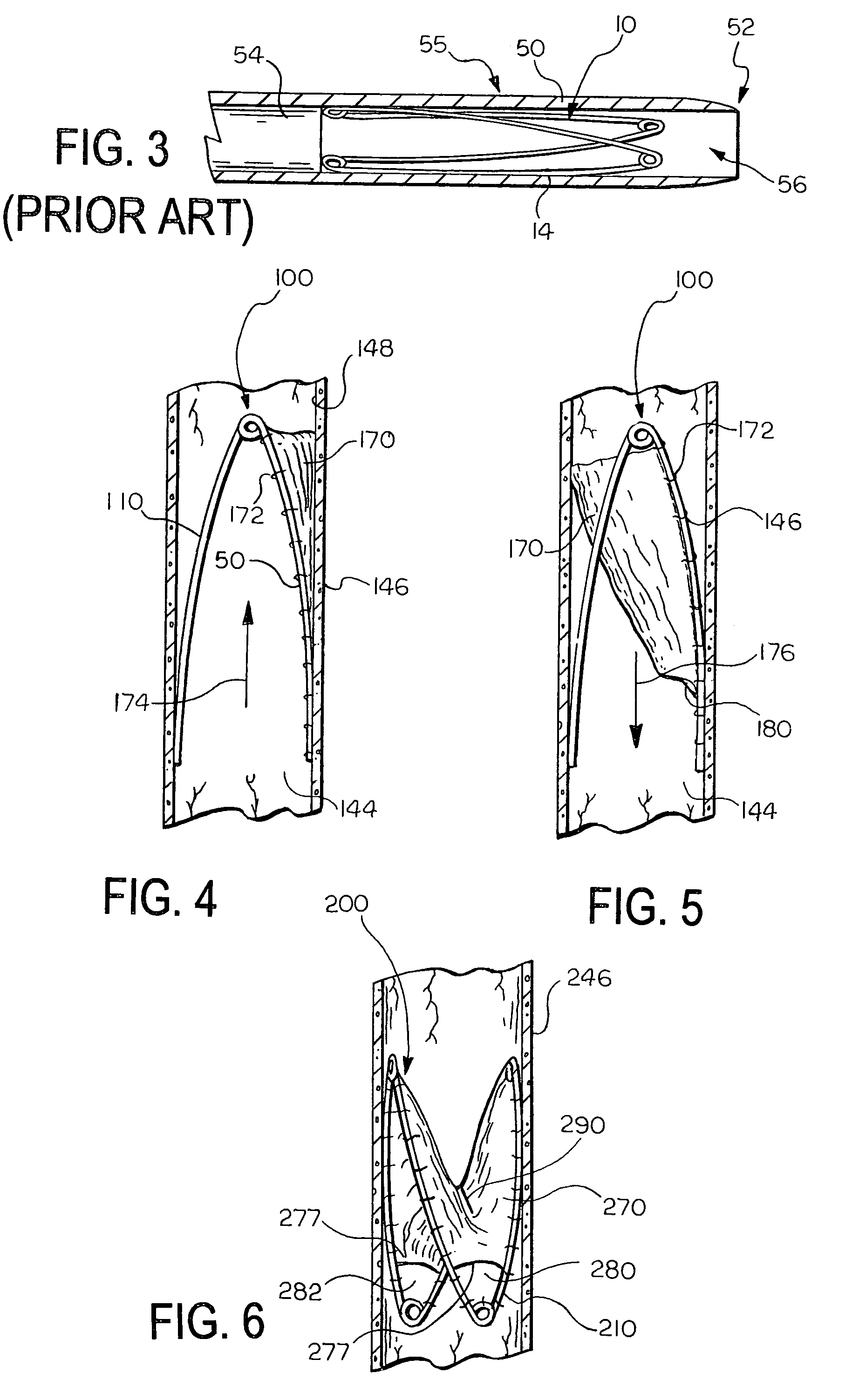
[0060]FIGS. 4 and 5 illustrate a medical device 100 according to the invention. The device 100 includes a support frame 110 and a valve leaflet 170 attached to the support frame 110. In this embodiment, the support frame 110 is the support frame 10 illustrated in FIGS. 1, 1A, 2, and 3.

[0061]The valve leaflet 170 comprises a section of material, such as a sheet, that is attached to the support frame 110. The valve leaflet 170 can be formed of any suitable material, and need only be biocompatible or be able to be made biocompatible. The material can advantageously be formed of a flexible material. Examples of suitable materials for the valve leaflet 170 include natural materials, synthetic materials, and combinations of natural and synthetic materials. Examples of suitable natural materials include extracellular matrix (ECM) materials, such as small intestine submucosa (SIS), and other bioremodellable materials, such as bovine pericardium. Other examples of ECM materials that can be u...

second embodiment

[0069]FIG. 6 illustrates a medical device 200 according to the invention. In this embodiment, the leaflet 270 spans the entire support frame 210, and includes a slit 290 that defines an aperture in the leaflet 270. The leaflet 270 opens and closes the slit 290 to permit flow in a first direction and substantially prevent flow in a second, opposite direction, i.e., retrograde flow, by moving the slit from a first open position to a second closed position. The slit 290 can be oriented relative to the frame 210 as shown, or in any other suitable orientation.

[0070]In this embodiment, the medical device 200 includes multiple openings 280, 282 for allowing a controlled amount of retrograde flow to pass through the device 200 when the slit 290 is in the second, closed position. Each of the openings 280, 282 is as described above for the first embodiment and the total cumulative open area of the openings 280, 282 is, at a maximum, less than the cross-sectional area of the vessel 246 at the ...

third embodiment

[0071]FIG. 7 illustrates a medical device 300 according to the invention. In this embodiment, the device 300 includes two leaflets 346, 348 that are attached to the support frame 310. Each leaflet 346, 348 has a free edge 350, 352 that is not attached to the support frame 310. The free edges 350, 352 cooperatively define valve orifice 392. The leaflets 346, 348 are both movable between first and second positions. In the first position, illustrated in FIG. 7, the orifice 392 is open and allows fluid flow through the device 300 in a first direction, represented by arrow 374. In the second position, the free edges 350, 352 of leaflets 346, 348 come together to close the orifice 392 and substantially prevent fluid flow through the device in a second, opposite direction.

[0072]Each leaflet 346, 348 defines an opening 380, 382 that allows a controlled amount of retrograde flow to pass through the medical device 300 when the valve orifice 392 is closed. In this embodiment, each of the openi...


PUM


Abstract

A prosthetic valve for regulating fluid flow through a body vessel is provided. The valve includes an expandable support frame and a valve leaflet, and includes at least one opening that permits a controlled amount of retrograde flow through the valve when the valve is in a closed configuration.

Description

CROSS-REFERENCE TO RELATED APPLICATIONS[0001]This application claims priority to U.S. Provisional Application Ser. No. 60 / 454,249, filed on Mar. 12, 2003, and U.S. Provisional Application Ser. No. 60 / 488,138, filed on Jul. 16, 2003, each of which is hereby incorporated into this disclosure in its entirety.FIELD OF THE INVENTION[0002]The present invention relates to medical devices. More particularly, the invention relates to intraluminal valve prostheses.BACKGROUND OF THE INVENTION[0003]Many vessels in animal bodies transport fluids from one bodily location to another. Frequently, fluid flows in a unidirectional manner along the length of the vessel. Varying fluid pressures over time, however, can introduce a reverse flow direction in the vessel. In some vessels, such as mammalian veins, natural valves are positioned along the length of the vessel and act as one-way check valves that open to permit the flow of fluid in the desired direction and close to prevent fluid flow in a rever...

Claims


Application Information

Patent Timeline
Patent Type & Authority Patents(United States)
IPC IPC(8): A61F2/24A61F2/06
CPCA61F2/2418A61F2/2475A61F2220/005A61F2230/0095A61F2220/0075A61F2230/0026A61F2220/0058A61F2/2412
Inventor OSBORNE, THOMAS A.CASE, BRIAN C.BLEYER, MARK W.PAUL, RAM H.
Owner COOK MEDICAL TECH LLC
Why Eureka
Try Eureka