System for the projection of cinematographic works and digital works with sound

a cinematographic and digital work technology, applied in the field of cinematographic work or digital work projection system, can solve the problems of affecting the quality of the image, treble and extreme treble, and inability to achieve small-sized screens,

a cinematographic and digital work technology, applied in the field of cinematographic work or digital work projection system, can solve the problems of affecting the quality of the image, treble and extreme treble, and inability to achieve small-sized screens,

US20060256985A1Active Publication Date: 2006-11-16PIERRE VINCENT 67 INTEREST +1

Image

  • System for the projection of cinematographic works and digital works with sound
  • System for the projection of cinematographic works and digital works with sound
  • System for the projection of cinematographic works and digital works with sound

Examples


Embodiment Construction

)

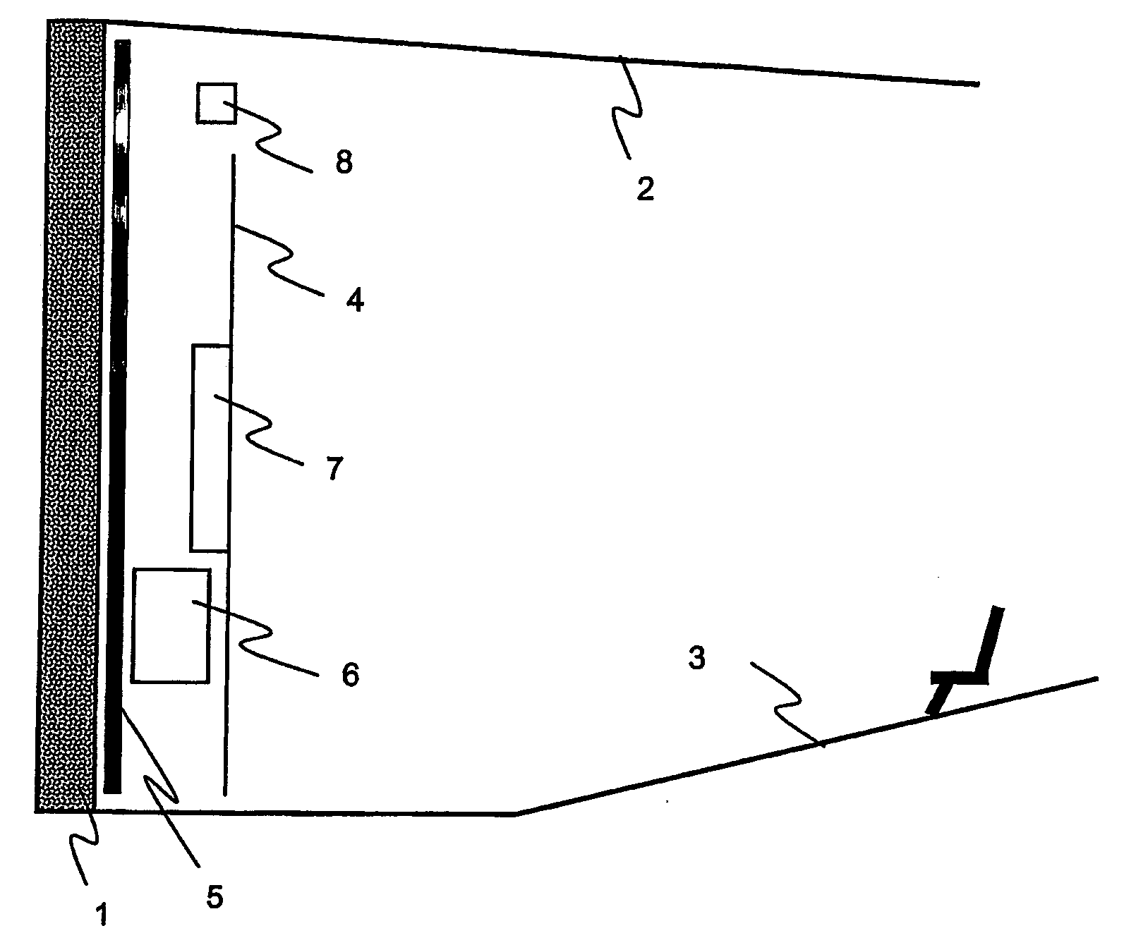
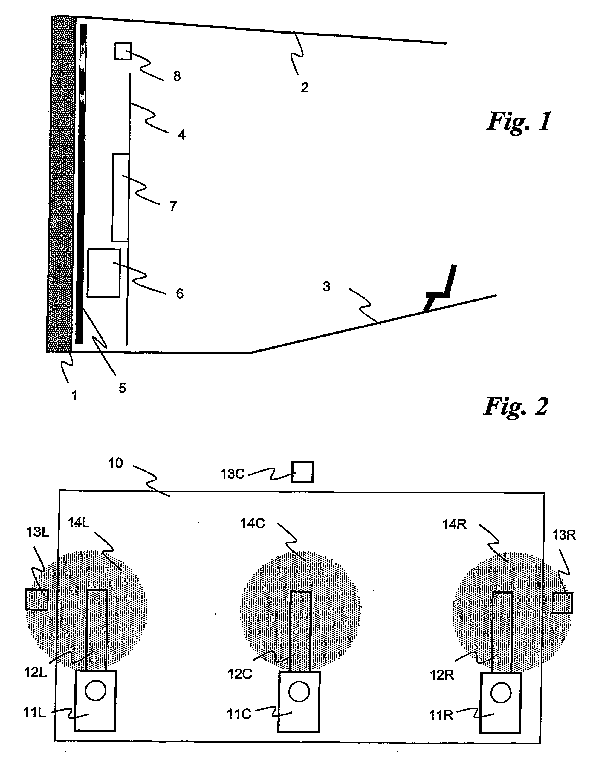
[0033]FIG. 1 shows a cinema projection room delimited in the cross-section by a back wall 1 a ceiling 2 and a floor 3.

[0034] The screen 4, which is not perforated, is disposed at a certain distance from the back wall 1. A plate 5 of a sound-absorptive material is disposed against the wall 1 on the side of the screen 4 in order to deaden sound reflections, essentially in the bass / medium frequency range.

[0035] A woofer 6 is disposed between the screen 4 and the panel 5 towards the bottom of the screen, this speaker being able to produce sounds with a frequency that is lower than around 500 Hz.

[0036] A medium / treble speaker 7, which is able to produce sounds in a range of around 500 Hz-4 kHz, is disposed above the woofer 6.

[0037] An extreme treble speaker 8 is disposed above the periphery of the screen, above the speakers 6 and 7, this speaker being able to produce sounds with a frequency that is higher than around 4 kHz.

[0038] The speaker 7 is a flat sound transducer, the active...


PUM


Abstract

A system for the projection of cinematographic works or digital works with sound having at least one sound channel. The system comprises a screen and, for the sound channel, at least one woofer and at least one medium / treble transducer. The screen is a non-perforated screen. The medium / treble speaker is a flat sound transducer placed against the screen to the rear thereof in relation to the direction of projection. An extreme treble speaker is disposed on the periphery of the screen.

Description

BACKGROUND OF THE INVENTION [0001] (1) Field of the Invention [0002] This invention relates to a system for the projection of cinematographic works or digital works with sound, and more specifically for such films with at least one sound channel, the said system comprising a screen and, for the said sound channel, at least one woofer and at least one medium / treble speaker. Hereinafter, sound channel will refer only to the screen channels, not including the environment channels which, in the invention, are treated in the conventional manner. [0003] (2) Prior Art [0004] There are normally three screen channels: a left channel, a central channel and a right channel. There are also systems with five channels including a middle-left channel and a middle-right channel. [0005] Finally, there are giant-screen systems with four channels, two of which are lateral channels and the other two are a central-high channel and a central-low channel. [0006] In conventional systems, each channel compr...

Claims


Application Information

Patent Timeline
16 Nov 2006
Publication
US20060256985A1
IPC
H04R5/02; G03B21/56; G03B31/00; H04R7/04
CPC
G03B21/565; G03B31/00; H04R2499/15; H04R7/04; H04R2205/024; H04R5/02; H04N5/74
Inventors
VINCENT