Watermarked polymeric sheet

a polymeric sheet and watermark technology, applied in the field of watermarking polymeric sheets, can solve the problems of inability to include variable information or data, complex and time-consuming process, and indistinct watermarks, etc., to achieve wide commercial acceptance, improve ink laydown and adhesion, and reduce surface energy

Inactive Publication Date: 2006-11-16
COOPER JONATHAN JAMES
View PDF5 Cites 2 Cited by
  • Summary
  • Abstract
  • Description
  • Claims
  • Application Information

AI Technical Summary

Benefits of technology

[0014] We have found that watermarks produced according to the present invention are distinct and well defined. The pattern may have any repeat length and can be simple or complex. Different watermarks can be generated very easily without having to alter or reconfigure the apparatus, simply by controlling the light source. The watermark may be adapted readily to include logos, pictures, text and variable information such as identification codes, dates and serial numbers.
[0024] The surface of the polymeric sheet may be treated chemically and / or by corona discharge for improved print acceptance.
[0040] The lack of absorption of films / sheets such as synthetic paper can be overcome by applying a coating comprising a major amount of a absorbent filler and a minor amount of an adhesive binder. The coating can be incorporated during the manufacturing process. Such a method yields a product that is receptive to print and such products have gained wide commercial acceptance. Where such coatings are inconvenient and expensive to apply and require a separate manufacturing process, or render the surface so treated susceptible to the adverse effects of water and solvents, a higher amount of a filler such as silica can be employed.

Problems solved by technology

A voiding agent such as zinc-calcium resinate is generally used, which causes voiding when a heated sheet of synthetic paper is stretched.
Although the process described in EP 0655316 may be used to make a watermarked product, we have found that the watermark is rather indistinct and not well defined.
If a different watermark or pattern is required, the roller must be changed, which is a complex and time-consuming process.
Another disadvantage is that the watermark cannot include variable information or data, such as an identification code, date or serial number.

Method used


Image

  • Watermarked polymeric sheet
  • Watermarked polymeric sheet
  • Watermarked polymeric sheet

Examples


example 1

[0070] The following composition was used to produce Compound A (used in the production of the base material):

Parts byComponentWtRigidex TM 002 / 55 HDPE copolymer (MFI 0.2 g / 10 min100& density 0.955 Kg / m3, ex BP Chemicals Ltd)Rigidex TM HD6070EA HDPE (MFI 7.5 g / 10 min &17.6density 0.96 Kg / m3, ex BP Chemicals Ltd)Polystyrene Grade HF888 (ex BP Chemicals Ltd)4.8DERTOLINE TM MP 1706.0Cariflex TM TR1102 Styrene-butadiene-styrene copolymer0.6(ex Shell UK Ltd)Anhyd.CaCO3 (2.5 μ particle size, OMYA ex Craxton & Garry)21.0TiO2 (Rutile) RCR2 (ex Tioxide)5.8Armostat TM 400 (antistat, ex Akzo Chemicals Ltd)0.14Armostat TM 375D (antistat, ex Akzo Chemicals Ltd)0.35Caloxal TM CPA (CaO, ex Sturge Lifford Ltd)0.58Calcium Stearate (ex RTZ Chemicals Ltd)0.04Irganox TM 8215 (antiox., ex Ciba-Geigy Ind Ltd)0.29

HDPE = High density polyethylene

MFI = Melt flow index

[0071] Compound A was prepared from the above components as follows: Separate, melt blended, cooled and diced masterbatches (A1 and B) wer...

example 2

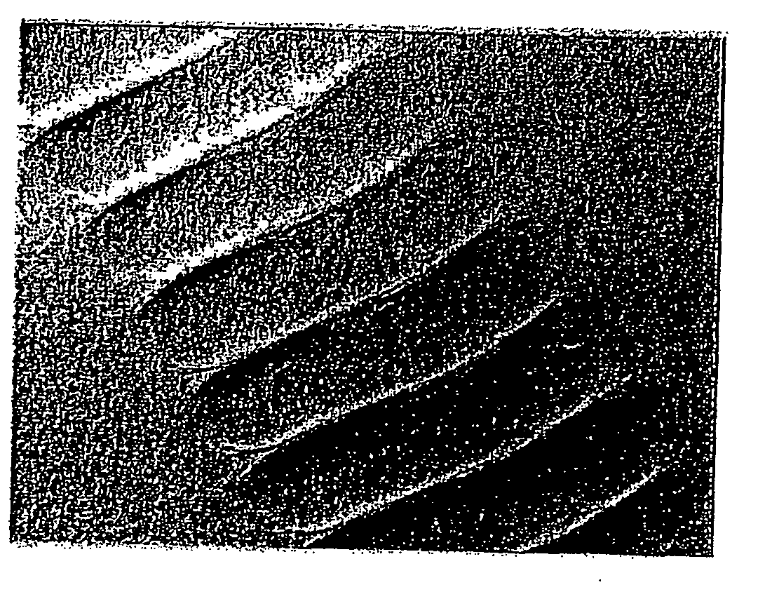
[0082] A composite co-extruded sheet was made using the same process and with the same composition as in Example 1. In this case, however, the laser was pulsed at a frequency of 500 Hz, with an on time of 1.6 ms and an off time of 0.4 ms. The angle of the laser was adjusted during operation, to cause lateral movement of the dot over the surface of the web (in the transverse direction).

[0083] The watermark produced by this process is shown in FIGS. 7, 8 and 9. As can be seen in FIG. 7, the watermark consists of a wavy line of dots running in the machine direction. The dots are closer together than in Example 1 and consist of elongate indentations in the surface of the web, having a width of about 3 mm and an average depth of about 18 μm. Magnified views of the indentations are provided in FIGS. 8 (by reflected light) and 9 (by transmitted light).

example 3

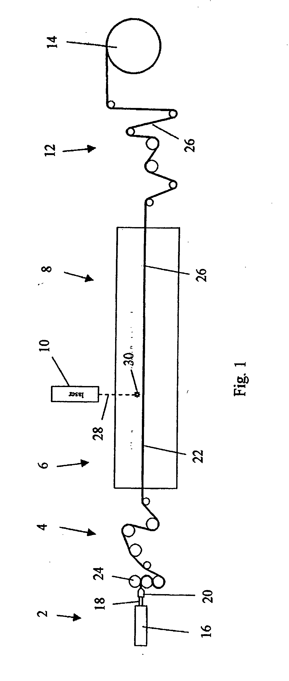
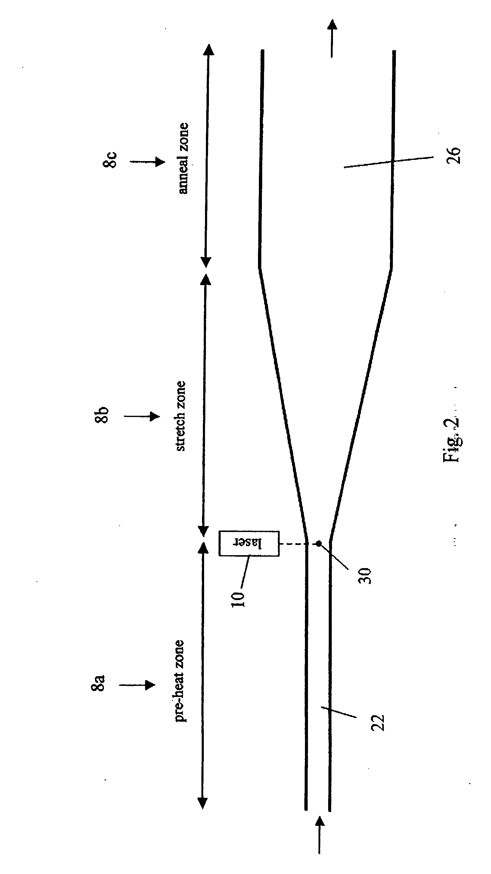
[0084] A composite co-extruded sheet was made using the same process and with the same composition as in Example 1. In this case, however, the laser 10 was mounted on a frame 40 above the oven and the laser beam 28 was directed onto the web using a scanner unit 42. The layout of the optical components was as shown in FIG. 10.

[0085] The laser 10 was mounted so that the laser beam 28 emerged in a direction parallel to the longitudinal axis of the oven. The beam was passed through a beam expander 44 and then reflected through 90° by a mirror 46 into the scanner unit 42, which was mounted above an access window 48 in the top wall of the oven. The scanner unit 42 was arranged to scan the laser beam in a transverse direction: i.e. perpendicular to the direction of travel of the web through the oven. The arrangement allowed for beam control, scanning and focusing of the beam onto the moving web. The beam expander 44 was adjusted to provide a spot size of 0.3-0.4 mm diameter on the surface...


PUM

PropertyMeasurementUnit
depthaaaaaaaaaa
depthaaaaaaaaaa
areaaaaaaaaaaa

Abstract

A watermarked polymeric sheet including a stretched sheet of a polymeric material having a plurality of indentations in at least one of its surfaces, the indentations including areas of increased translucency, which form a watermark that is visible by transmitted light.

Description

RELATED APPLICATIONS [0001] This application is a divisional of application Ser. No. 10 / 943,733, filed Sep. 17, 2004, which claims priority to GB 0321822.9, filed Sep. 18, 2003. The contents of these applications are incorporated herein by reference in their entireties.BACKGROUND OF THE INVENTION [0002] 1. Field of the Invention [0003] The present invention relates to a watermarked polymeric sheet and a method of making the same. In particular, but not exclusively, the invention relates to a watermarked synthetic paper and a method of making a watermarked synthetic paper. [0004] 2. Description of the Related Art [0005] In this specification, the term “watermark” means a mark formed from areas of increased and / or decreased translucency that is visible by transmitted light and resembles a conventional watermark in a sheet of cellulose-based paper. The terms “watermarked” and “watermarking” should be construed accordingly. [0006] The term “synthetic paper” is used herein and throughout...

Claims


Application Information

Patent Timeline
Patent Type & Authority Applications(United States)
IPC IPC(8): B32B3/00B29C35/08B29C55/06B29C59/16B41M3/10
CPCB29C55/06B29C59/16Y10T428/24479B41M3/10B29C2035/0838B29C55/16B32B2038/0028B32B2310/0843B32B27/16B32B27/32B32B2554/00B32B38/0012B32B2310/14B32B27/205
Inventor COOPER, JONATHAN JAMES
Owner COOPER JONATHAN JAMES
Why Eureka
Try Eureka