Floor construction covered with ceramic tiles

Active Publication Date: 2006-11-23
SCHLUTER SYST LP
View PDF30 Cites 63 Cited by
  • Summary
  • Abstract
  • Description
  • Claims
  • Application Information

AI Technical Summary

Benefits of technology

[0005] It is therefore an object of the invention to reduce the height of such a

Problems solved by technology

Applying such a tile to a liquid floor pavement is not possible.
Such an application,

Method used


Image

  • Floor construction covered with ceramic tiles
  • Floor construction covered with ceramic tiles
  • Floor construction covered with ceramic tiles

Examples


Embodiment Construction

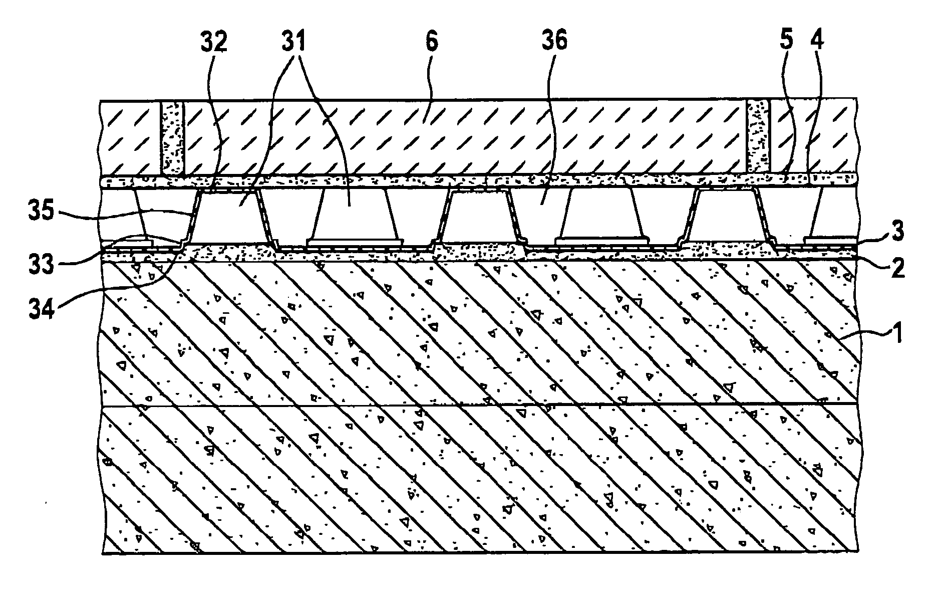
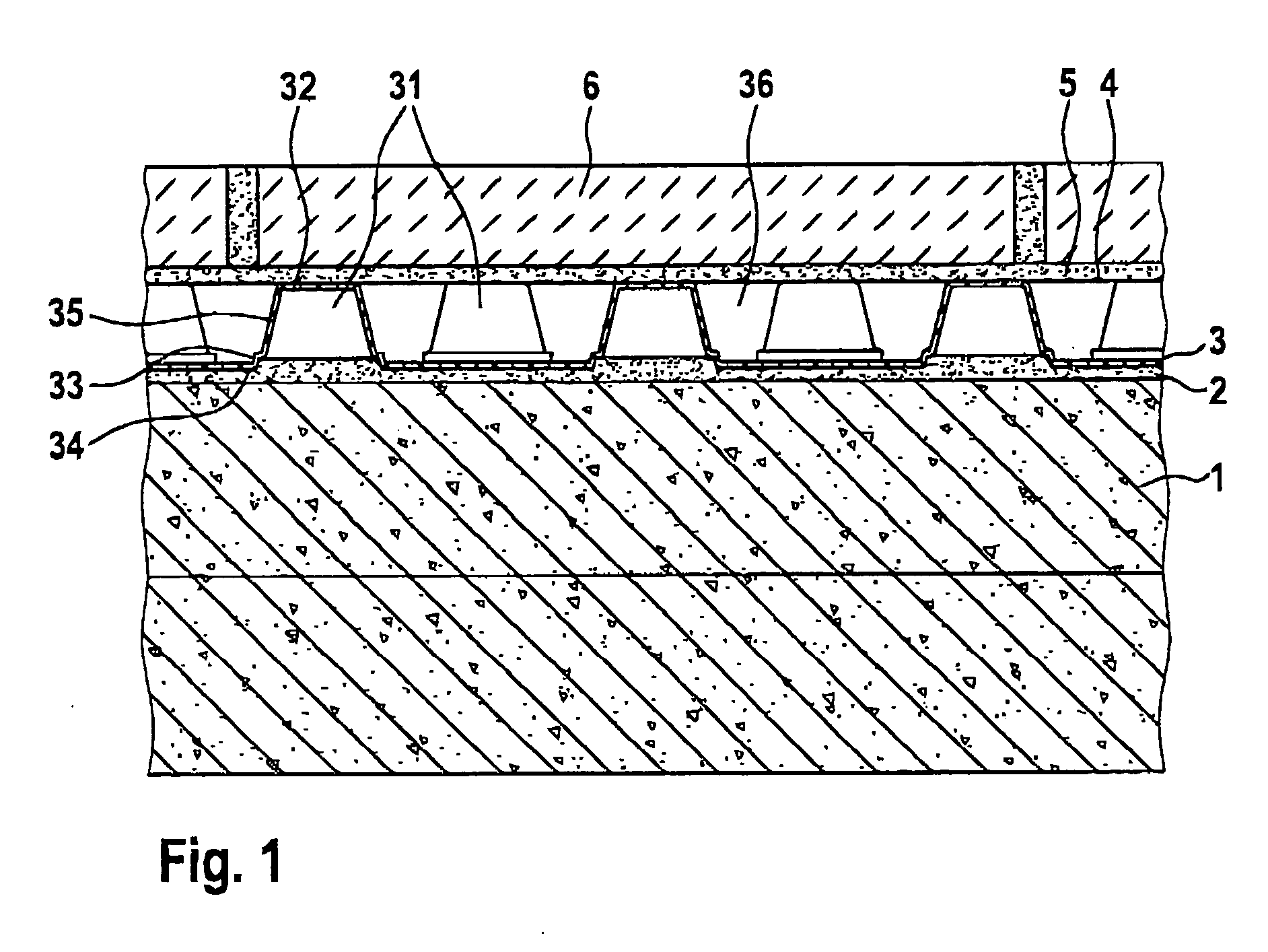
[0016] First, reference will be made to FIGS. 1 and 2. On a suitable sub-floor 1, for example a concrete plate having a hardened gradient floor pavement, a hardening thin-bed mortar layer 2 is applied in the manner of a tile adhesive or another corresponding priming mass. In this thin-bed mortar 2, which has not yet hardened, a film-like plastic mat 3 is embedded with its underside, in such a manner that its contact surfaces 33, 34 that are available on the underside are completely supported, with a correspondingly level, i.e. horizontal arrangement.

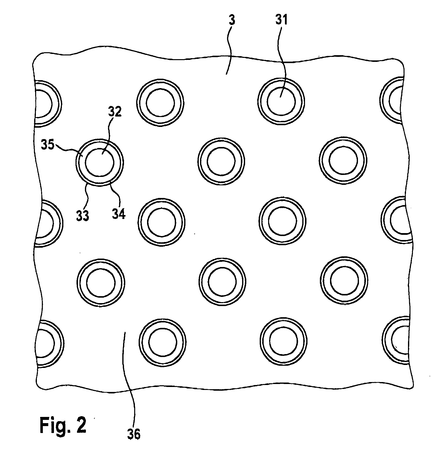
[0017] Plastic mat 3 shown in FIGS. 1 and 2 is a nub panel, in which hollow nubs 31 that project upward, in the shape of a truncated cone, are formed with a uniform area distribution, with tops 32. Between these nubs, open channels 36 are formed for water removal towards the outside. The embedded contact surfaces 34 that serve for support are enlarged by means of steps 33 in the transition region from contact surfaces 34 to nub walls 35...


PUM


Abstract

A floor construction covered with ceramic tiles, in which a film-like plastic mat having support elements disposed in a uniform area distribution, hollow towards the underside, capable of support, projecting out beyond the top of the mat, is applied on the sub-floor. Channels carrying open water are formed between the support elements, and a water-permeable or vapor-permeable covering in the manner of a non-woven fabric or woven fabric is disposed on the support elements. The plastic mat is embedded and attached, supported in a still soft, hardening thin-bed mortar layer on the sub-floor, over its full area, in the region of its lower contact surfaces. The ceramic tiles are laid and attached on the covering in the manner of a non-woven fabric, directly, with a thin-bed mortar layer.

Description

BACKGROUND OF THE INVENTION [0001] 1. Field of the Invention [0002] The invention relates to a floor construction covered with ceramic tiles, in which a film-like plastic mat having support elements disposed in a uniform area distribution, hollow towards the underside, capable of support, projecting out beyond the top of the mat, is applied on the sub-floor. Channels carrying open water are formed between the support elements, and a water-permeable or vapor-permeable covering in the manner of a non-woven fabric or woven fabric is disposed on the support elements, above which ceramic tiles laid using the adhesive method are disposed. [0003] 2. The Prior Art [0004] Such a floor construction is known from German Patent No. DE 90 11 271 U1. In this connection, a film-like plastic mat in the manner of a nub panel is loosely laid onto the sub-floor, for example a concrete plate or a hardened gradient floor pavement. Applying such a tile to a liquid floor pavement is not possible. Such an ...

Claims


Application Information

Patent Timeline
IPC IPC(8): E04B1/70
CPCE04F15/18E04F15/08E04F15/185E04F15/182
Inventor SCHLUTER, WERNER
Owner SCHLUTER SYST LP
Why Eureka
Try Eureka