Method of manufacturing a compressible structural panel with reinforcing dividers

a technology of compressible structural panels and reinforcing dividers, which is applied in the field of structural panels to achieve the effects of convenient installation, uniform thickness, and thin thickness or profil

Inactive Publication Date: 2006-11-23
CERTAINTEED CEILING
View PDF76 Cites 23 Cited by
  • Summary
  • Abstract
  • Description
  • Claims
  • Application Information

AI Technical Summary

Benefits of technology

[0011] As will be appreciated, with a panel so formed, it will assume an expanded form in its normal at rest condition, but by applying pressure, with a perpendicular component, to the outer sheet or the connector, the dividers are caused to compress allowing the entire panel to assume a very thin thickness or profile. When compressing, the outer sheet is moved perpendicularly toward the connector sheet with the dividers being compressed therebetween, i.e. there is minimal, if any, sliding movement between the outer and connector sheets. This, of course, is very advantageous for shipping purposes as a greater number of panels can be confined in a container than is possible with prior art panels that have a uniform thickness during shipping and use. The panels are also predominantly air filled and, therefore, are very lightweight.
[0012] It will further be appreciated from the more detailed description hereafter that the panels can be bent at least in one direction to facilitate installation in a drop ceiling or the like but are resilient to resume their normal at rest position. Further, the panels are not brittle and do not damage easily. They can, further, be cut very simply into any predetermined size and / or configuration.

Problems solved by technology

The panels are also predominantly air filled and, therefore, are very lightweight.

Method used


Image

  • Method of manufacturing a compressible structural panel with reinforcing dividers
  • Method of manufacturing a compressible structural panel with reinforcing dividers
  • Method of manufacturing a compressible structural panel with reinforcing dividers

Examples


second embodiment

[0155] With reference to FIGS. 33-35, a panel 94 is illustrated wherein the connector sheet 54 has been replaced with a connector in the form of a plurality of elongated flexible but non-extensible strands or fibers 96. These strands or fibers could be plastic, nylon or other similar material having the same or similar characteristics. The strands or fibers of material can be adhesively or otherwise bonded to tubular dividers 52′ while extending transversely thereto and with the fibers spaced from each other preferably in parallel relationship to each other. A panel 94 so formed can be easily flexed or bent, as illustrated in FIG. 35, in a direction transverse to the longitudinal direction of the dividers as with the previously described panel.

[0156] In each of the afore-described embodiments of the invention, the dividers have identical side partitions 98 (FIGS. 12 and 34) which have longitudinal fold lines 100 therein so that the side partitions fold inwardly when the panel is com...

third embodiment

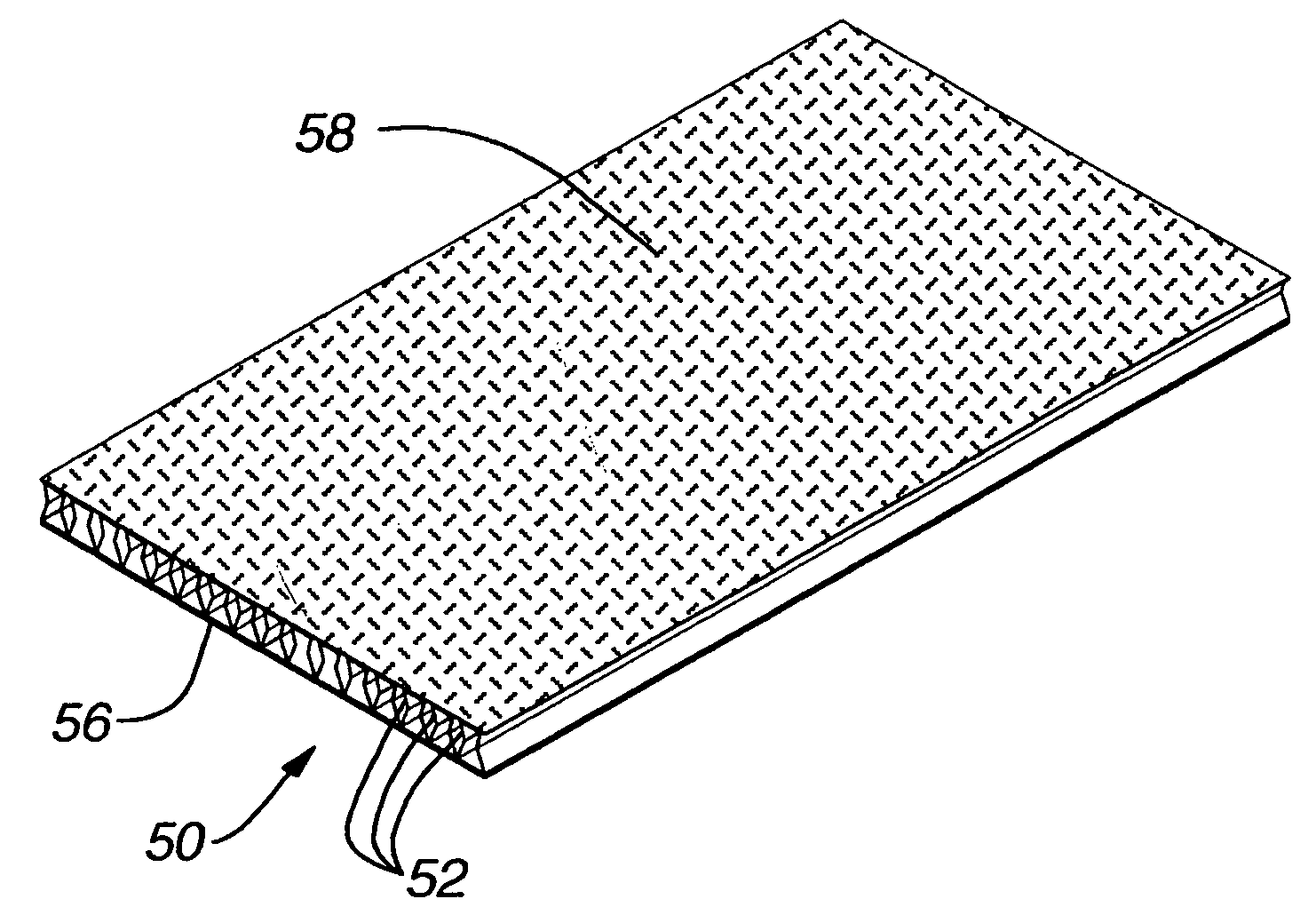
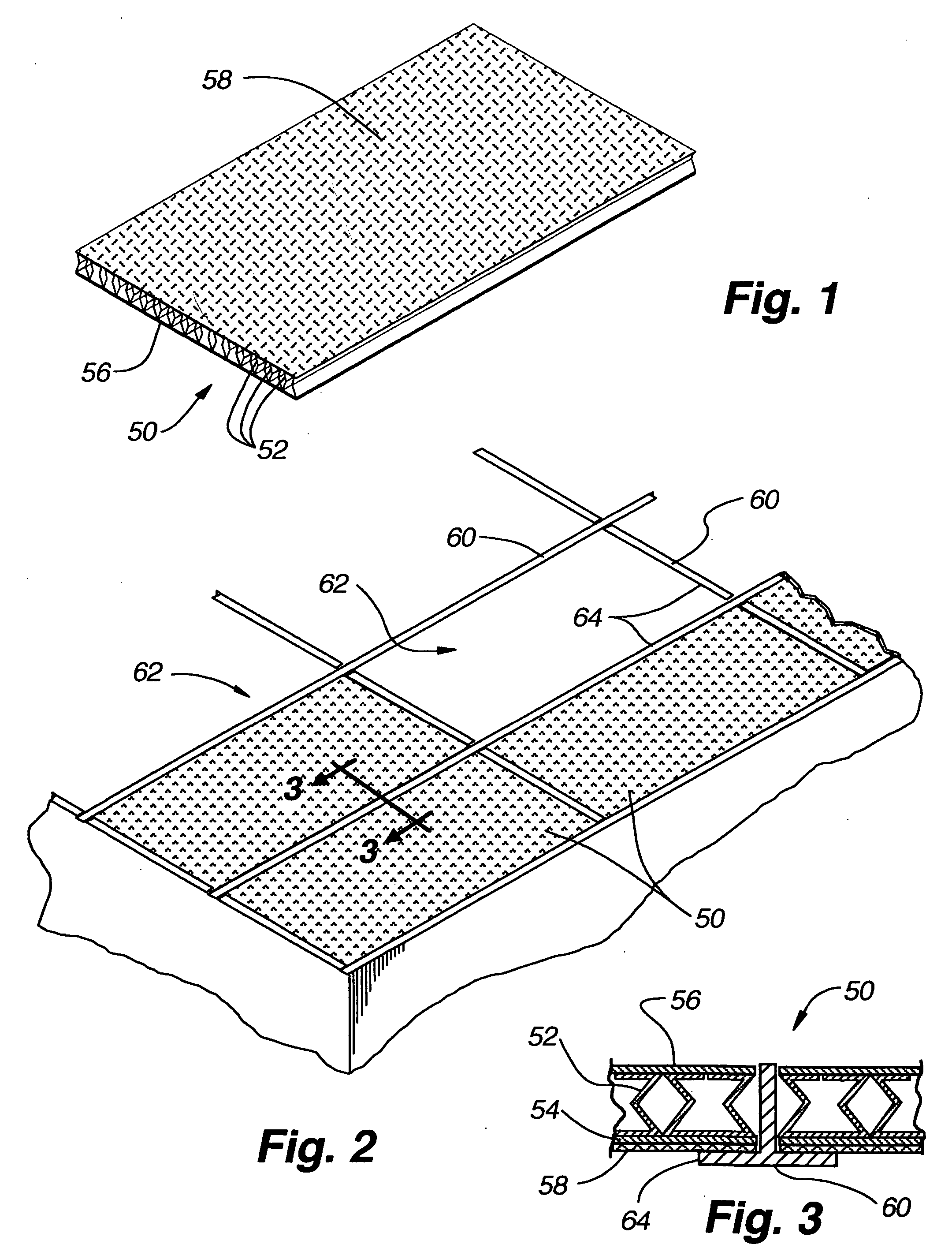
[0157] the present invention is illustrated in FIGS. 36-42 and in this embodiment, a panel 102 is identical to that shown in FIG. 12 except that the partitions 104 in the dividers 105 are symmetric in configuration. In other words, the panel 102 includes an outer sheet 54′ and a connector sheet 56′ interconnected by dividers with partitions and may include a decorative panel 58′ overlying the outer sheet if desired. Fold lines 106 along the partitions 104, however, are positioned so that an upper rectangular portion 104a of each partition is of equal size to a lower rectangular portion 104b. The panel 102 can again be compressed.

[0158] The compressed and expanded forms of the panel 102 shown in FIGS. 36-38 are illustrated isometrically in FIGS. 39 and 40 and it will be appreciated that the panel can be fully compressed to a depth or side profile that is far less than its normal expanded condition.

[0159] As seen in FIGS. 41 and 42, when the panels are stacked, a considerable amount ...

first embodiment

[0162] By changing the location of the fold line 106 in each side partition of a divider 105, the resistance of the panel to compression can also be regulated. For example, in the at rest expanded position of an asymmetric panel 50 such as disclosed as the present invention and shown in FIGS. 43 and 45, an obtuse angle “a” is formed in the side partition 98 which is greater than the corresponding angle “d” in the partition 104 as shown in FIG. 46 of a symmetric panel. The height A of each panel in the expanded form is, however, identical. Note also the difference in the length B and C of the upper and lower portions 98a and 98b, respectively, of the side partitions of the asymmetric divider, whereas in the symmetric divider illustrated in FIG. 46, the length D of the upper partition portion 104a and the lower partition portion 104b are identical.

[0163] The greater the angle “a” or “d” in the side partition, the more resistance there will be to compressing the panel, as illustrated i...


PUM


Abstract

A structural panel for use in building structures or in the formation, finish or decoration thereof includes an outer sheet and a connector sheet with a plurality of collapsible or compressible dividers therebetween. The panel in a rest condition is expanded and of a desired thickness for final use but can be compressed into a relatively thin thickness or profile for shipping purposes. The panel is very lightweight but structurally strong and can be selectively bent in one transverse direction if desired. The panel can be easily cut or formed into any predetermined size or shape.

Description

CROSS REFERENCE TO RELATED APPLICATIONS [0001] This application is a continuation of U.S. application Ser. No. 10 / 309,939 filed Dec. 3, 2002, which is a continuation-in-part of U.S. application Ser. No. 09 / 970,008, filed Sep. 27, 2001, which is a continuation of U.S. application Ser. No. 09 / 839,373, filed Apr. 23, 2001, which application claims the benefit of U.S. provisional application No. 60 / 199,208, filed Apr. 24, 2000. This application also relates to co-pending application Ser. No. 10 / 309,944 filed Dec. 3, 2002 entitled “Method and Apparatus For Fabricating Cellular Structural Panels”. All of the above-identified applications are hereby incorporated by reference as if fully disclosed herein.BACKGROUND OF THE INVENTION [0002] 1. Field of the Invention [0003] A structural panel which finds particular uses as a ceiling panel or wall panel, includes an outer sheet having a plurality of spaced dividers protruding from one face thereof and a connecting sheet, or the like, parallel t...

Claims


Application Information

Patent Timeline
Patent Type & Authority Applications(United States)
IPC IPC(8): E04C2/54E04B9/00E04B9/04E04B9/26E04C2/34
CPCE04B9/001E04B9/0414E04B9/0428E04B9/0435E04B9/0442Y10T428/24149E04B9/0457E04B9/26E04B2009/0492E04C2/3405Y10T428/24661E04B9/045
Inventor SWISZCZ, PAUL G.KUPERUS, KOCOLSON, WENDELL B.THRONE, JASON T.
Owner CERTAINTEED CEILING
Why Eureka
Try Eureka