Pulse detonation assembly with cooling enhancements

a technology of pulse detonation and cooling enhancement, which is applied in the direction of intermittent jet plants, lighting and heating apparatus, combustion types, etc., can solve the problems that neither of these techniques are acceptable for the practical application the overheating and noise problems of pulse detonation engines, so as to achieve the effect of enhancing heat transfer

Inactive Publication Date: 2006-11-23
GENERAL ELECTRIC CO
View PDF21 Cites 55 Cited by
  • Summary
  • Abstract
  • Description
  • Claims
  • Application Information

AI Technical Summary

Problems solved by technology

However, pulse detonation engines are subject to both overheating and noise problems.
Neither of these techniques is acceptable for practical applications of pulse detonation engines.

Method used


Image

  • Pulse detonation assembly with cooling enhancements
  • Pulse detonation assembly with cooling enhancements
  • Pulse detonation assembly with cooling enhancements

Examples


Embodiment Construction

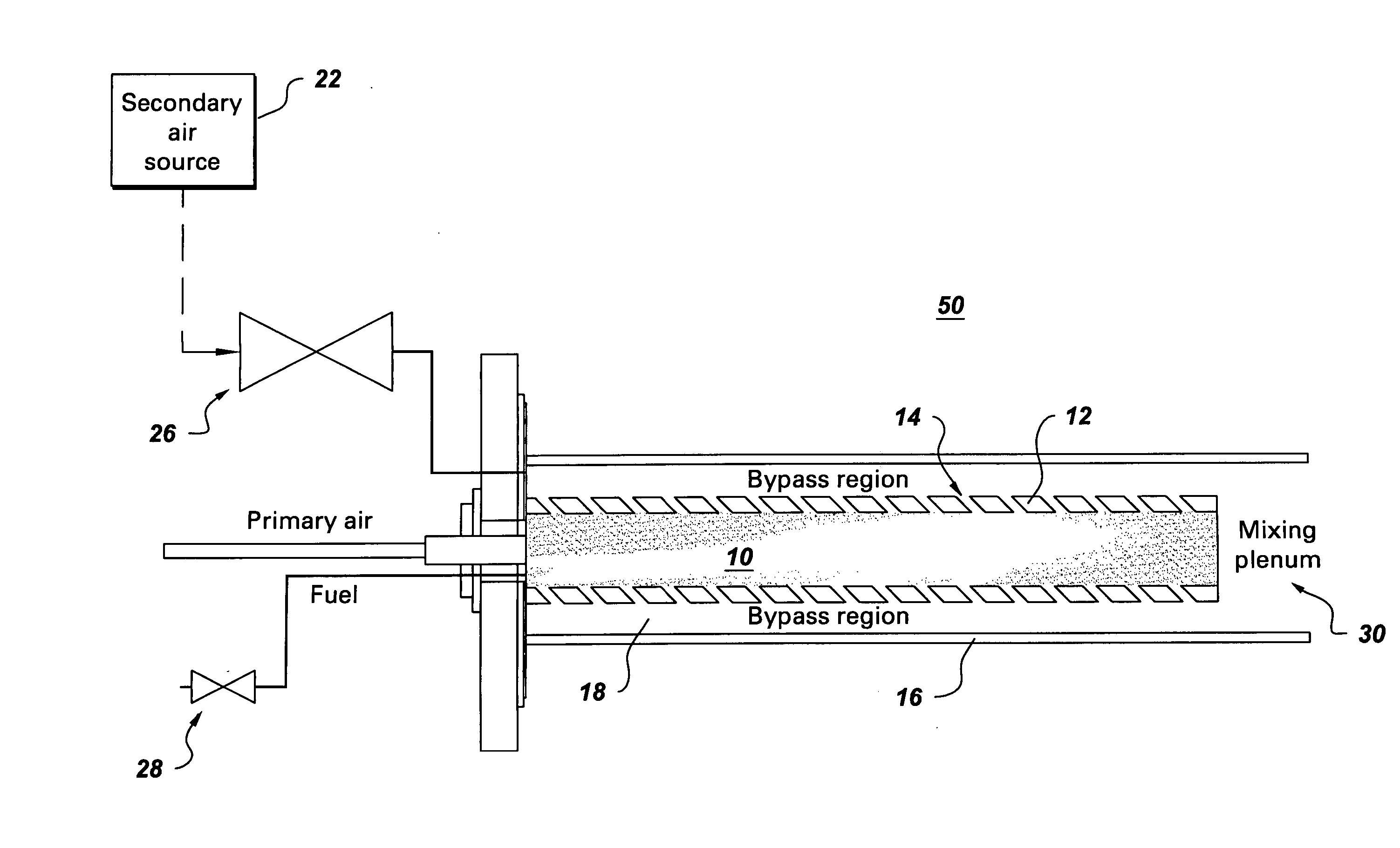
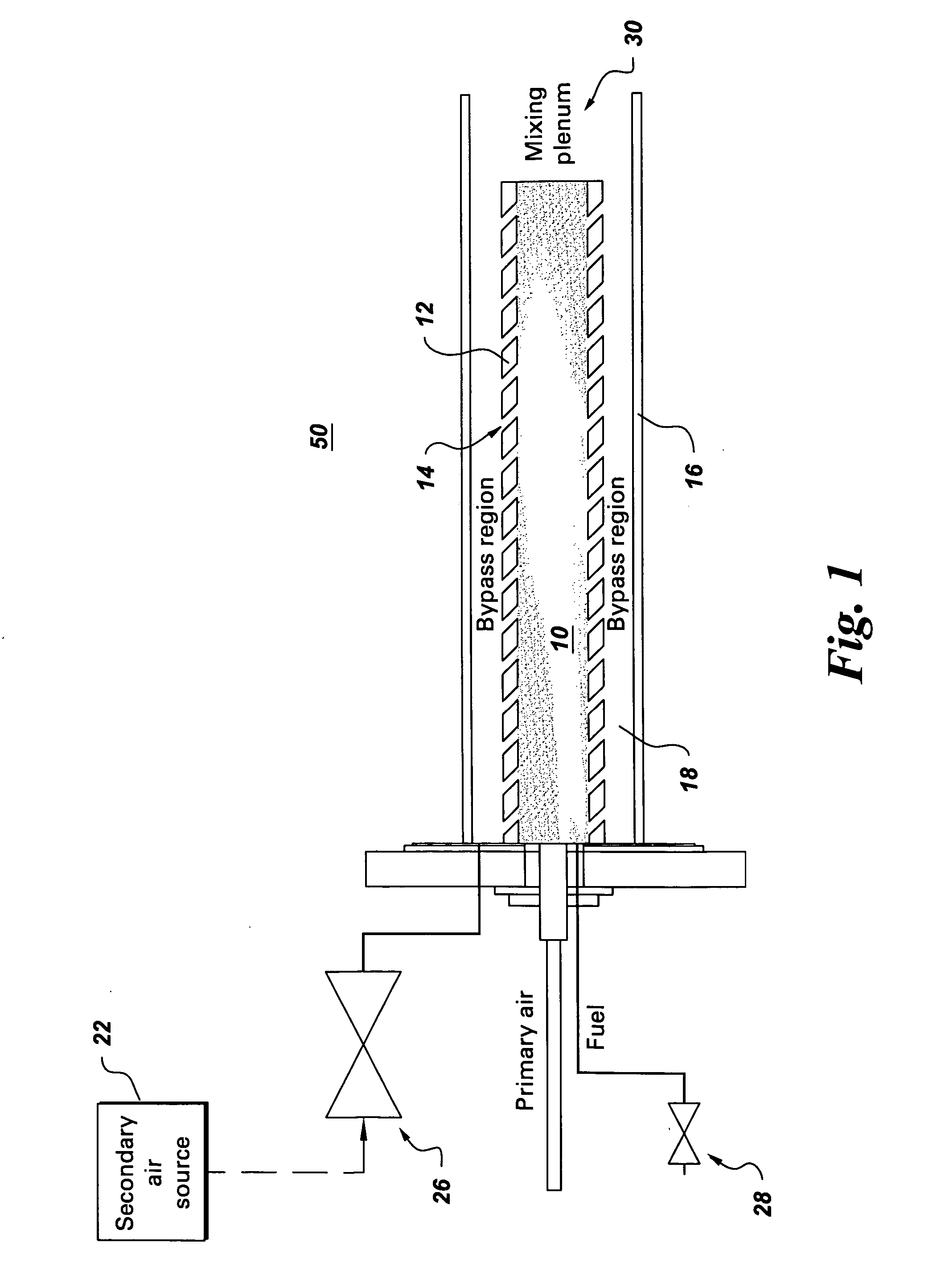
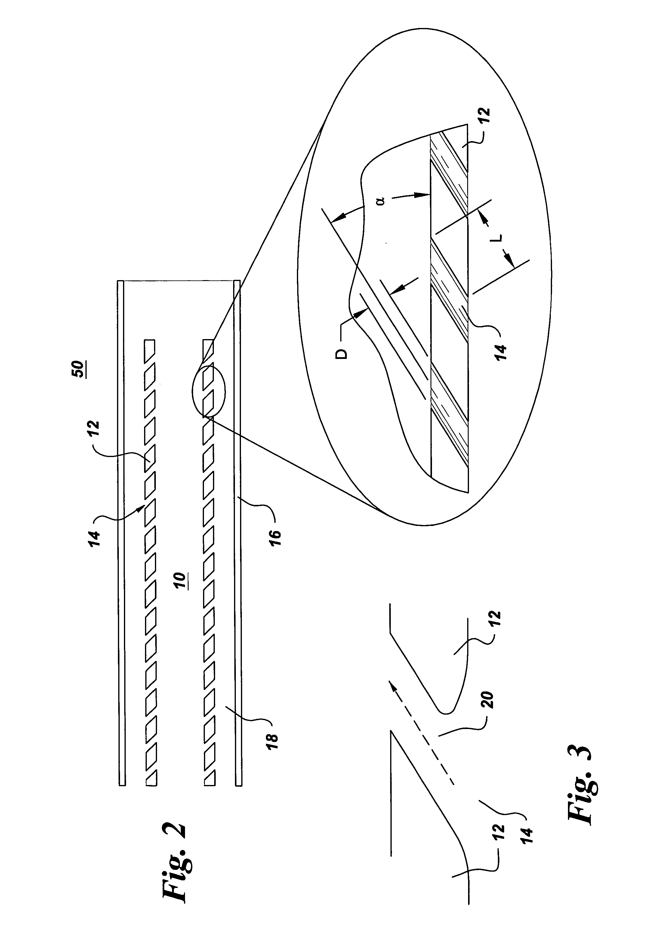
[0016] A first pulse detonation (PD) assembly 50 is described with reference to FIG. 1. As shown, PD assembly 50 includes at least one PD chamber 10, which has a wall 12 that defines a number of cooling holes 14. Cooling holes 14 are arranged along at least a portion of PD chamber(s) 10. PD assembly 50 further includes a manifold 16 (for example, an annular manifold) extending around PD chamber 10. Manifold 16 and PD chamber(s) 10 are separated by a bypass region 18.

[0017] As used herein, a “pulse detonation chamber” (or “PD” chamber) is understood to mean any combustion device or system where a series of repeating detonations or quasi-detonations within the device cause a pressure rise and subsequent acceleration of the combustion products as compared to the pre-bumed reactants. A “quasi-detonation” is a combustion process that produces a pressure rise and velocity increase higher than the pressure rise produced by a deflagration wave. Typical embodiments of PD chambers include a ...


PUM


Abstract

A pulse detonation (PD) assembly includes at least one PD chamber having a wall, which defines cooling holes arranged along at least a portion of the PD chamber. A manifold extends around the PD chamber. The manifold and PD chamber are separated by a bypass region. A PD assembly with reverse flow cooling includes at least one PD chamber. A sleeve extends around the PD chamber. The sleeve and PD chamber are separated by a reverse flow cooling passage configured to receive a flow of air and to flow the air in a reverse direction to supply the PD chamber. A PD assembly with bypass flow cooling includes at least one PD chamber and a manifold extending around the PD chamber(s), which are separated by a bypass region. The PD assembly further includes a mixing plenum configured to receive and mix the bypass flow from the bypass region and the detonation by-products from the PD chamber(s).

Description

BACKGROUND [0001] The invention relates generally to pulse detonation assemblies, and more particularly, to cooling enhancements for pulse detonation assemblies. [0002] Pulse detonation engines are a promising propulsion and power generation technology, in view of the lower entropy rise of detonative processes, as compared to constant pressure deflagration. Consequently, pulse detonation engines have the potential to propel vehicles at higher thermodynamic efficiencies than are achieved with deflagration-based engines. [0003] However, pulse detonation engines are subject to both overheating and noise problems. For experimental or prototype applications, overheating is typically prevented by operating the pulse detonation tube for only a short period of time, typically in the range of seconds. Noise has been addressed for experimental or prototype arrangements by performing tests in closed, acoustically treated test cells. Neither of these techniques is acceptable for practical appli...

Claims


Application Information

Patent Timeline
Patent Type & Authority Applications(United States)
IPC IPC(8): F02C5/00
CPCF02C5/00F02K7/02F02K7/06Y02T50/675F23R7/00F05D2260/202F23C15/00Y02T50/60
Inventor VANDERVORT, CHRISTIAN LEERASHEED, ADAMDEAN, ANTHONY JOHNTANGIRALA, VENKAT ESWARLUPINARD, PIERRE FRANCOISWIEDENHOEFER, JAMES FREDRIC
Owner GENERAL ELECTRIC CO
Why Eureka
Try Eureka