Railroad car lateral instability and tracking error detector

a technology for detecting lateral instability and tracking errors, which is applied in railway auxilary equipment, railway signalling, transportation and packaging, etc., can solve problems such as increased derailment risk, excessive suspension wear, and damage to lading carried by railroad vehicles

Inactive Publication Date: 2006-11-23
PROGRESSIVE RAIL TECH
View PDF13 Cites 36 Cited by
  • Summary
  • Abstract
  • Description
  • Claims
  • Application Information

AI Technical Summary

Benefits of technology

[0040] Another aspect of the present invention is to provide a reliable computer algorithm that evaluates the set of wheel set lateral position sensor readings to detect an oscillating pattern indicating lateral instability.

Problems solved by technology

Excessive suspension wear.
Damage to lading carried by railroad vehicles, particularly finished automobiles, electronic products or any items that are sensitive to sustained vibrations.
Increased derailment risk.
Increased fuel consumption of trains with hunting cars.
This design is inherently unstable as the wheel set rolls on the rails as shown in FIGS. 1a and 1b.
However, due to insufficient damping forces in this simple mechanical system the wheel set will tend to oscillate laterally around its equilibrium position, as shown in FIG. 1a.
Lateral instability tends to increase as railroad car weight decreases and speed increases.
Unfortunately these methods also tend to degrade the ability of railroad car suspensions to negotiate curves, and they increase the cost and maintenance of railroad car suspensions.
Thus, the vast majority of freight railroad cars in service in North America are not equipped with any special equipment to control wheel set lateral instability.
Truck tracking errors occur when one or more wheel sets in a truck run with a lateral offset toward one rail or the other.
These “on-board” methods of detecting and quantifying lateral instability are not practical for the large number of railroad cars in operation on the freight railroads.
Certain track maintenance activities destroy the lateral force sensors.
The lateral force sensors are susceptible to voltage surges that propagate along the rails.
Lighter railroad cars may generate lateral wheel forces that are below the sensitivity threshold of the sensors and will not be detected even though the railroad car wheel sets are laterally unstable.
The disadvantage of this prior art is the complexity and cost of the laser / camera range finder system and the need for periodic cleaning and maintenance.

Method used


Image

  • Railroad car lateral instability and tracking error detector
  • Railroad car lateral instability and tracking error detector
  • Railroad car lateral instability and tracking error detector

Examples


Embodiment Construction

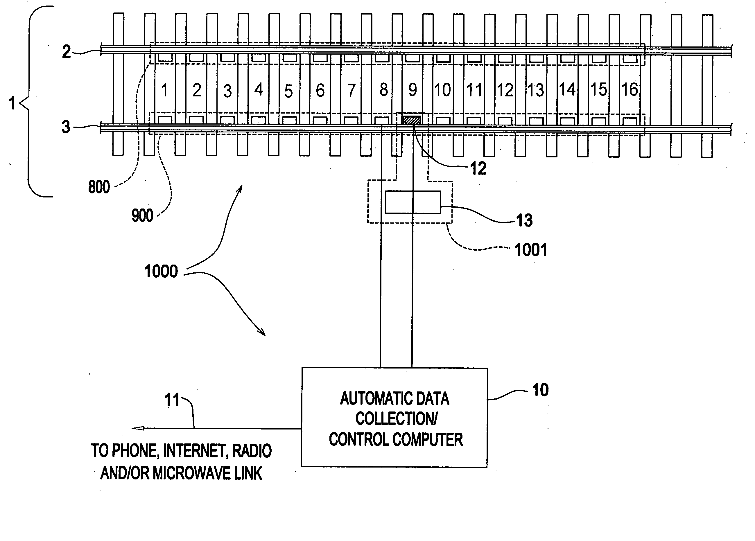
[0120] The preferred embodiment of the invention to detect lateral instability and tracking errors in North American freight railroad train service is shown in FIG. 4 and consists of:

[0121] 1. Arrays of 16 inductive proximity sensor pairs 8,9 mounted on the left and right rails 2,3 of a railroad track 1 with a spacing of approximately 24 inches between sensor pairs.

[0122] 2. Inductive proximity sensors 8,9 with a nominal detection range of 50 mm, an internal switching relay, a switching frequency of at least 250 Hz. and an operating voltage range of 10-30 VDC.

[0123] 3. Inductive proximity mounting brackets (14-17 in FIGS. 6a, 6b) that mount the inductive proximity sensors on the rails such that the sensor face resides 1.60 inches below the top of rail and centered laterally 2.34 inches from the inside edge of the rail head.

[0124] 4. A railroad car identification system 1001 in FIG. 4 comprised of the radio identification tag reader 13 and wheel detector 12.

[0125] 5. An automati...


PUM


Abstract

The current invention is intended to be installed in revenue service railroad tracks to detect railroad cars exhibiting wheel set lateral instability. The invention utilizes an array of inductive proximity sensors mounted at regular intervals in a section of railroad track. Each proximity sensor is oriented to sense the lateral position of railroad car wheel sets. The invention employs a computer algorithm to extrapolate the trajectory from the set of proximity sensor signals for each wheel set. A second algorithm evaluates the shape of the trajectory to detect oscillating lateral motion of the wheel set. A third algorithm assesses the severity of any wheel set lateral oscillations that are detected. An additional function of the invention is to detect railroad car trucks that exhibit “tracking errors”.

Description

CROSS REFERENCE APPLICATIONS [0001] This application is a non-provisional application claiming the benefits of provisional application No. 60 / 682,537 filed on May 19, 2005.FIELD OF INVENTION [0002] The present invention relates to using a series of inductive proximity sensors to determine the trajectory of railroad car wheel sets over a section of straight railroad track. The trajectory is analyzed to determine if the wheel sets exhibit an unstable lateral motion or exhibit eccentric lateral tracking positions relative to the track. BACKGROUND OF THE INVENTION [0003] Freight and passenger railroad car wheel sets can develop sustained lateral oscillations, commonly referred to as high-speed lateral instability or “hunting”, while operating on railroad track at elevated speeds. The consequences of wheel set lateral instability include: [0004] 1. Excessive suspension wear. [0005] 2. Damage to lading carried by railroad vehicles, particularly finished automobiles, electronic products or...

Claims


Application Information

Patent Timeline
Patent Type & Authority Applications(United States)
IPC IPC(8): B61D1/00
CPCB61F5/386B61K9/12B61F9/00
Inventor MACE, STEPHEN E.HANDAL, STEPHEN N.MARTIN, ROBERT W.
Owner PROGRESSIVE RAIL TECH
Why Eureka
Try Eureka