

Hydraulic antivibration device arrangement, hydraulic antivibration device, and car body side bracket
- Summary
- Abstract
- Description
- Claims
- Application Information
AI Technical Summary
Benefits of technology
Problems solved by technology
Method used
Image

Examples
first embodiment
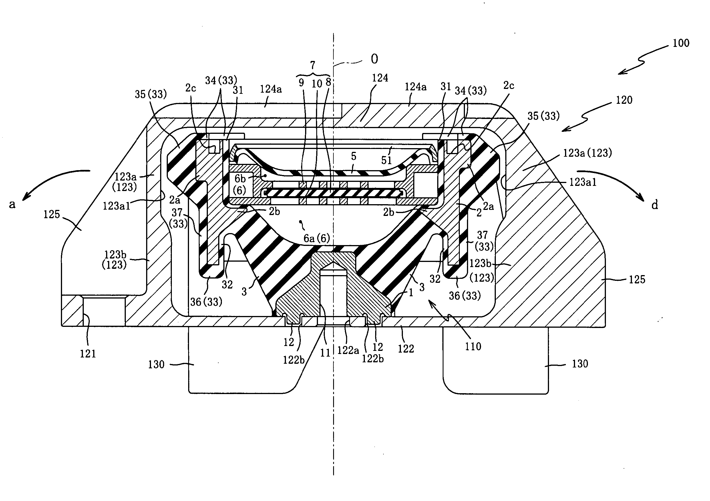
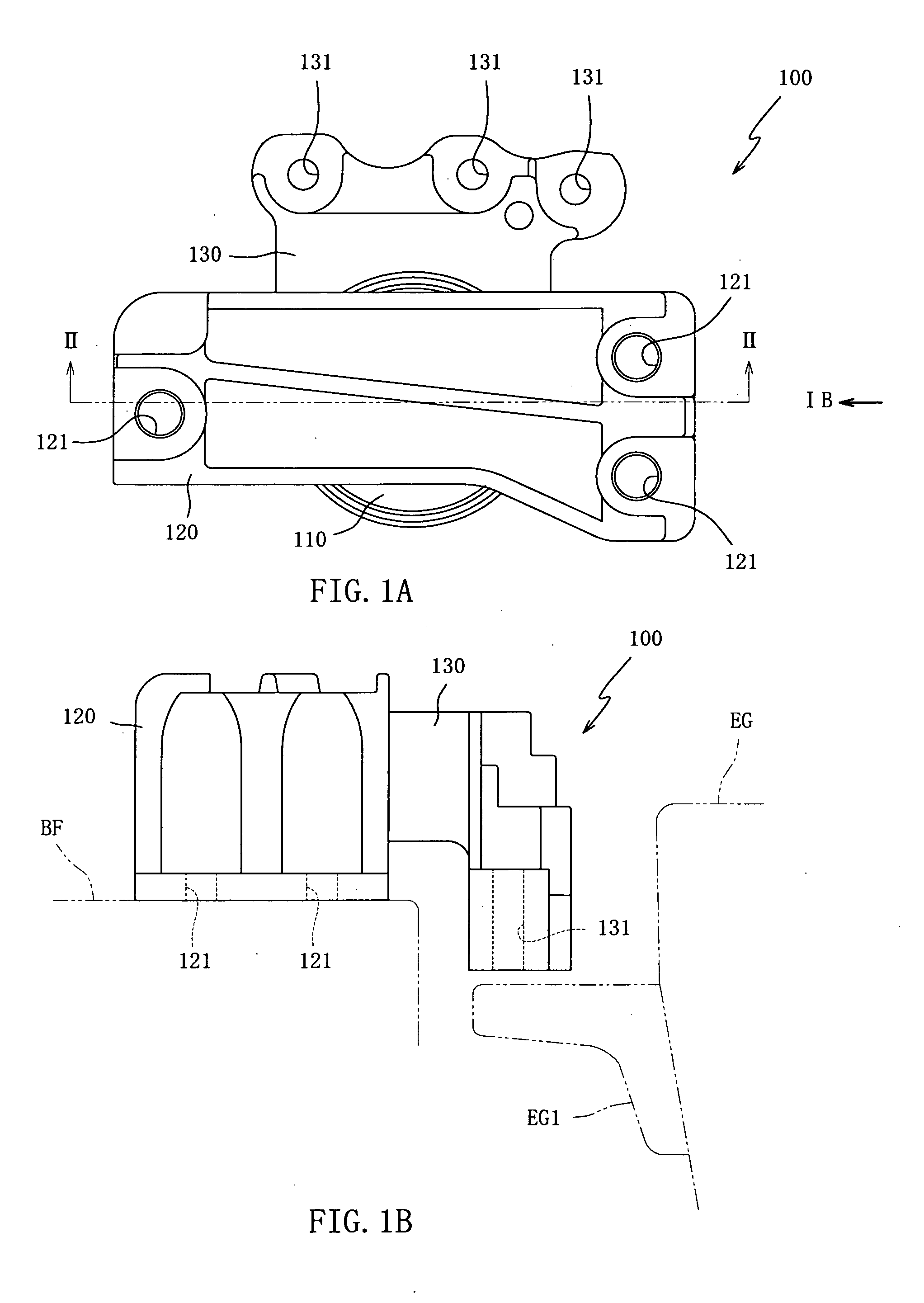
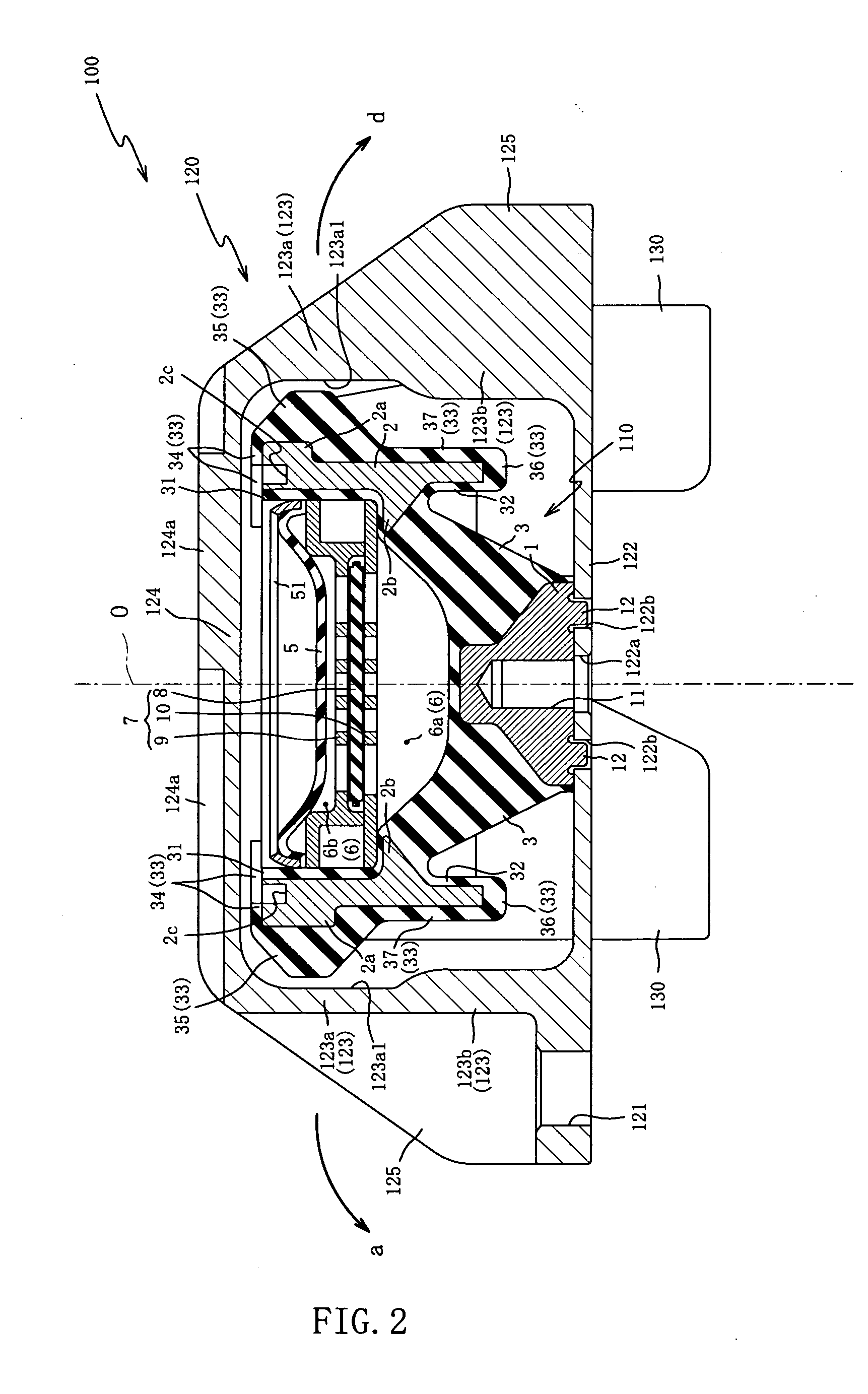
[0064] Preferred embodiments of the invention will be hereinafter described with reference to the accompanying drawings. FIG. 1(a) is a top plan view of the hydraulic antivibration device arrangement 100 in a first embodiment, and FIG. 1(b) is a side elevation of the hydraulic antivibration device arrangement 100 when viewed from the arrow mark direction Ib in FIG. 1(a).
[0065] The hydraulic antivibration device arrangement 100 is a hydraulic style vibration isolator for supporting the engine EG for automobiles in a cantilever suspended manner so as to prevent vibrations of the engine EG from being transmitted to the body frame BF. As shown in FIG. 1, it is mainly made up of the hydraulic antivibration device 110, the car body side bracket 120 connecting the hydraulic antivibration device 110 to the body frame BF side, and the engine side bracket 130 connecting the hydraulic antivibration device 110 to the engine EG side.
[0066] The car body side bracket 120 is adapted to be locked a...
second embodiment
[0152] One piece of the protruding pin 212 in the second embodiment is provided from the boss member 1 as illustrated in FIG. 8(a), and configured in an elongated hole shape having linear lines mutually parallel with both lateral faces, as viewed in the front elevation.
[0153] On the other hand, the slit portion 222b is, as shown in FIG. 8(b), formed as a recessed groove or slot, which is extended rectilinearly from a marginal edge portion of the bottom face part 122. The width of the slit portion 222b is formed to be the same as or somewhat larger than the width dimension of the protruding pin 212. The depth of the slit portion 222b is made shallower than the height of the protruding pin 212, but the depth may be made deeper than the height.
[0154] The slit portion 222b is formed, at its terminal end in the extended direction, with the abutment portion 222b1 in a semicircular shape, as illustrated in FIG. 8(b), and constructed so that the bolt through-hole 122a of the bottom face pa...
PUM
 Abstract
Description
Claims
Application Information