Gas generating system

Inactive Publication Date: 2006-11-23
AUTOMOTIVE SYST LAB
View PDF99 Cites 43 Cited by
  • Summary
  • Abstract
  • Description
  • Claims
  • Application Information

AI Technical Summary

Benefits of technology

[0005] In another aspect of the invention, a gas generating system is provided including a housing having a longitudinal axis and a pair of opposed ends, and a bulkhead positioned between the housing ends for partitioning the housing into a first chamber and a second chamber isolated from the first chamber so as to prevent fluid communication with the first chamber. A first baffle tube is positioned within the first chamber. The first baffle tube has a pair of opposed ends. A first pair of opposed surfaces is formed within the first chamber. Each surface of the first pair of opposed surfaces is sloped with respect to the longitudinal axis and abuts a corresponding end of the first baffle tub

Problems solved by technology

However, positioning the baffles to engage the shoulders or tabs during assembly of the gas generating system may be time consuming, thereby increasing assembly time and manufacturing costs.

Method used


Image

  • Gas generating system
  • Gas generating system
  • Gas generating system

Examples


Embodiment Construction

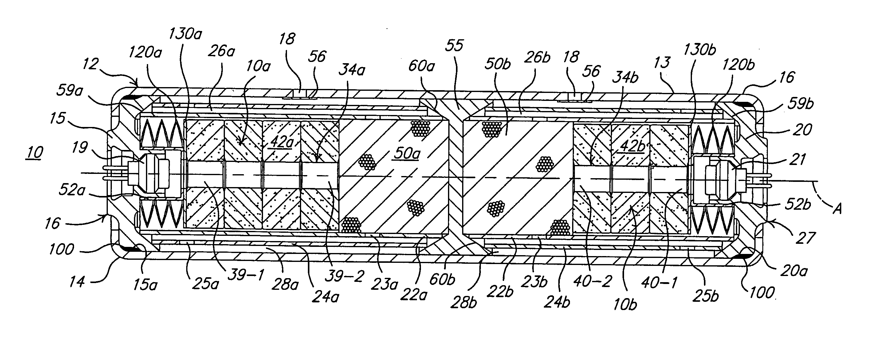
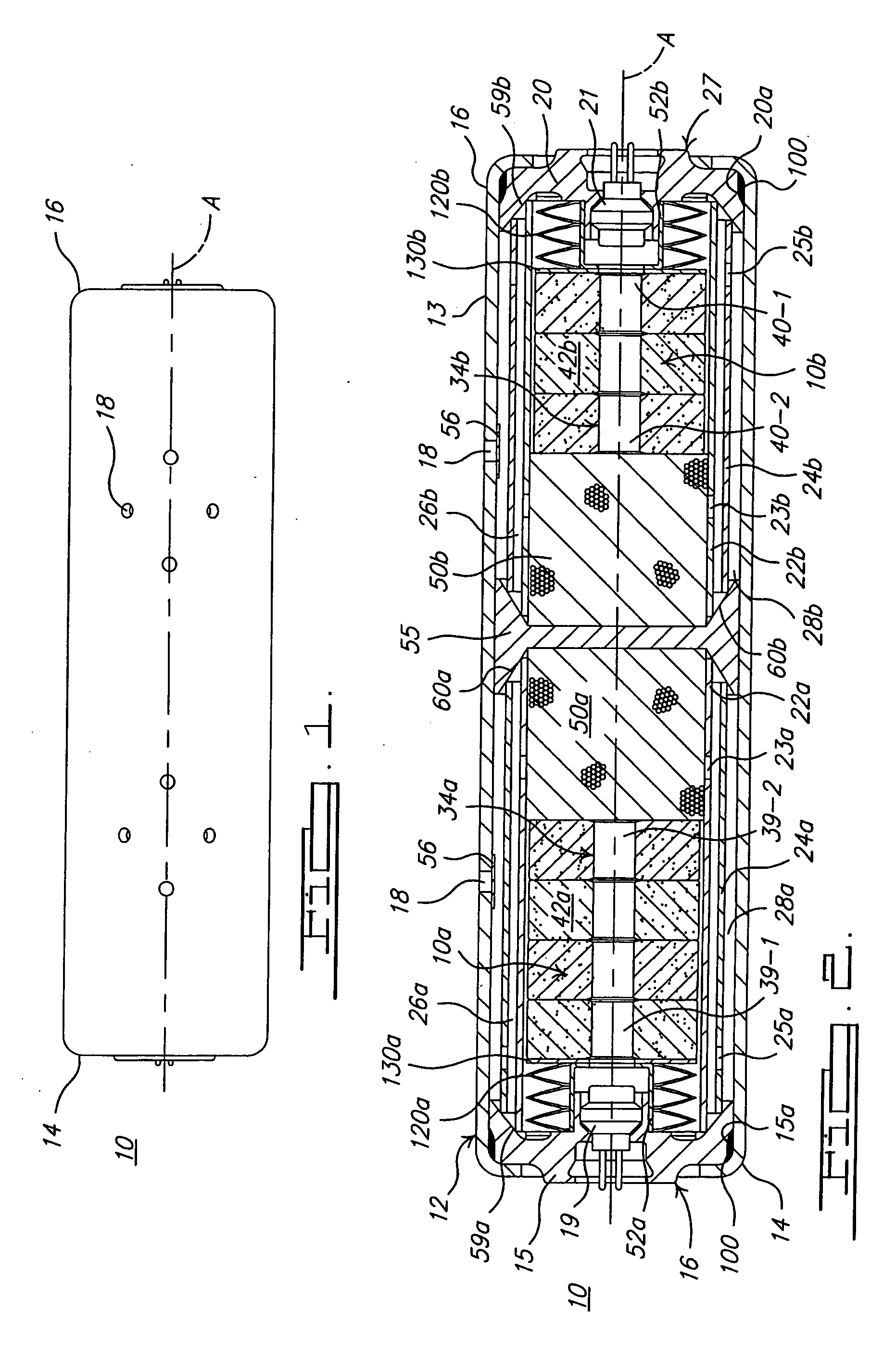
[0009]FIGS. 1-2 show one embodiment of a gas generating system 10 in accordance with the present invention. Referring to FIGS. 1-2, gas generating system 10 includes an elongate, substantially cylindrical housing 12, such as is well known in the art. Housing 12 has a first end 14 and a second end 16. A plurality of gas discharge apertures 18 are spaced circumferentially along housing 12 to enable fluid communication between an interior of the housing and an exterior of the housing, the exterior of the housing being in fluid communication with an airbag (not shown) or other inflatable element of a vehicle occupant restraint system. Housing 12 also has a longitudinal central axis A, an outer wall 13, and openings formed at both ends of housing 12. The housing may be stamped, extruded, die cast, or otherwise metal formed and may be made from aluminum, low carbon steel, or any other metal / alloy that is not gas permeable and that does not fragment during the burning of the gas generant e...


PUM


Abstract

A gas generating system (10) is provided including a housing (12) with a longitudinal axis (A), and a first baffle tube (22a) positioned within the housing (12) and having a pair of opposed ends. A second baffle tube (24a) is also positioned within the housing (12) and has a pair of opposed ends. A first pair of opposed surfaces (59a, 60a) is formed within the housing (12). Each of the first pair of opposed surfaces (59a, 60a) is sloped with respect to the longitudinal axis (A) and abuts a corresponding end of the first baffle tube (22a) to position the first baffle tube (22a) within the housing (12) such that a longitudinal axis of the first baffle tube (22a) is substantially coaxial with the longitudinal axis (A) of the housing (12). Each of the first pair of opposed surfaces (59a, 60a) also abuts a corresponding end of the second baffle tube (24a) to position the second baffle tube (24a) within the housing (12) such that a longitudinal axis of the second baffle tube (24a) is substantially coaxial with the longitudinal axis (A) of the housing (12). A vehicle occupant protection system (180) including the gas generating system (10) is also disclosed.

Description

CROSS REFERENCE TO RELATED APPLICATIONS [0001] This application claims the benefit of provisional application Ser. No. 60 / 655,061 filed on Feb. 22, 2005.BACKGROUND OF THE INVENTION [0002] The present invention relates to gas generating systems and, more particularly, to a multi-stage gas generating system for use in a vehicle occupant protection system. [0003] Some gas generating system designs incorporate one or more concentric, tubular baffles positioned within the gas generator housing to direct the flow of gases within the housing prior to expulsion of the gases from the housing. The baffles, usually in conjunction with an outer wall of the gas generator housing, form one or more concentric annular flow passages for channeling gas flow within the housing. In many of these designs, it is important to maintain the concentricity of the baffles during the flow of gases therethrough, to control the dimensions of the gas flow passages formed along the baffles. Concentricity of the baf...

Claims


Application Information

Patent Timeline
IPC IPC(8): B60R21/26
CPCB60R2021/2648B60R21/2644
Inventor BLACKBURN, JEFFERY S.
Owner AUTOMOTIVE SYST LAB
Why Eureka
Try Eureka