
Stator of linear motor

Inactive Publication Date: 2006-11-23
LG ELECTRONICS INC
View PDF5 Cites 12 Cited by
  • Summary
  • Abstract
  • Description
  • Claims
  • Application Information

AI Technical Summary

Benefits of technology

[0022] Therefore, the present invention has been made in view of the above problems, and it is an object of the present invention to provide a stator of a linear motor having a predetermined insulation distance between each outer core and a coil block, thereby effectively accomplishing insulation and heat transfer.
[0033] According to the present invention, the stator of the linear motor is formed such that each outer core block, the inner circumferential surface of which is opposite to the outer circumferential surface of the coil block, has an inner diameter equal to the outer diameter of the coil block. As a result, a minimum insulation distance is secured between each outer core block and the coil block. Consequently, the size of the linear motor is minimized, and insulation and heat transfer efficiencies are improved.
[0034] Also, each outer core block comprises first and second side core blocks and a center core block, and the inner diameter of the first and second side core blocks is different from that of the center core block. As a result, the first and second side core blocks are spaced a predetermined gap from the inner core. Consequently, efficiency of the linear motor is maintained, and the center core block is spaced a minimum insulation distance from the coil block.
[0035] Moreover, the insulating member is disposed between the outer core and the coil block. As a result, heat transfer is accomplished from the coil to the outer core through the insulating member. Consequently, heat sink efficiency is improved.
[0036] In addition, the center core block is provided with a heat sink part, which is inserted in the coil block for dissipating heat from the coil block. Consequently, heat generated from the coil block is effectively dissipated.
[0037] Furthermore, the insulating members are disposed between the heat sink part and the first coil and between the heat sink part and the second coil, respectively. Consequently, insulation efficiency is improved, and heat sink efficiency is also improved.

Problems solved by technology

As a result, heat transfer efficiency is deteriorated.
As a result, the insulating member is damaged.

Method used


Image

  • Stator of linear motor
  • Stator of linear motor
  • Stator of linear motor

Examples


Embodiment Construction

[0051] Now, preferred embodiments of the present invention will be described in detail with reference to the accompanying drawings.

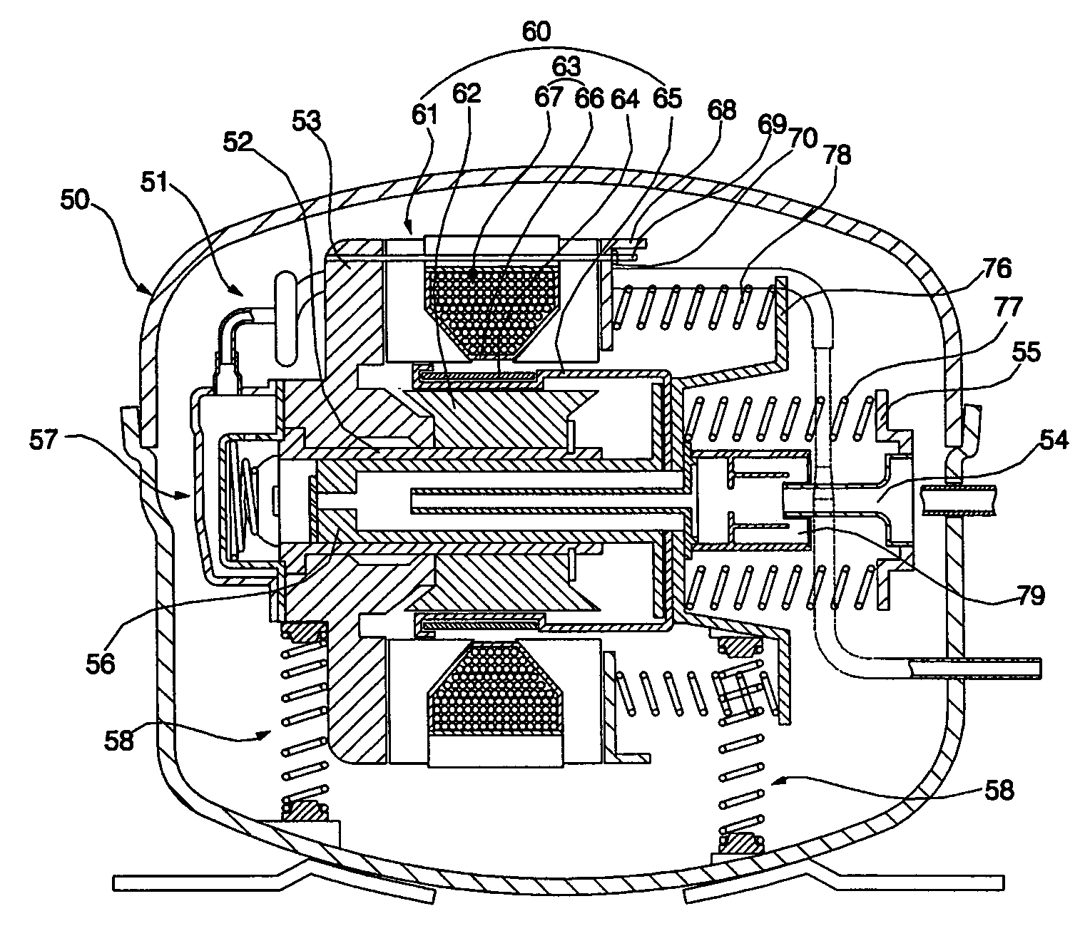
[0052]FIG. 5 is a longitudinal sectional view illustrating a linear compressor with a linear motor according to a first preferred embodiment the present invention mounted therein, FIG. 6 is a perspective view illustrating a stator of the linear motor according to the first preferred embodiment of the present invention, FIG. 7 is a cross-sectional view of the stator of the linear motor according to the first preferred embodiment of the present invention shown in FIG. 6, FIG. 8 is a longitudinal sectional view of the stator of the linear motor according to the first preferred embodiment of the present invention shown in FIG. 6, and FIG. 9 is a perspective view illustrating an outer core block constituting the stator of the linear motor according to the first preferred embodiment of the present invention.

[0053] Referring to FIG. 5, the linear compressor w...


PUM


Abstract

Disclosed herein is a stator of a linear motor having a plurality of outer core blocks. Each of the outer core blocks comprises first and second side core blocks and a center core block. The center core block has an inner diameter equal to an outer diameter of a coil block. Consequently, insulation and heat transfer efficiencies are improved, and the size of the linear motor is minimized. Furthermore, the center core block is provided with a heat sink part, which is inserted in the coil block for dissipating heat from the coil block. Consequently, heat generated from the coil block is effectively dissipated.

Description

BACKGROUND OF THE INVENTION [0001] 1. Field of the Invention [0002] The present invention relates to a linear motor, and, more particularly, to a stator of a linear motor having a plurality of outer core blocks wherein each outer core block comprises first and second side core blocks and a center core block, and the center core block has an inner diameter equal to an outer diameter of a coil block, whereby insulation and heat transfer efficiencies are improved, and the size of the linear motor is minimized. [0003] 2. Description of the Related Art [0004] Generally, a linear compressor is an apparatus that introduces, compresses, and discharges refrigerant gas (hereinafter, referred to as “fluid”) through a linear reciprocating movement of a piston in a cylinder, which is performed by a linear driving force of a linear motor. [0005]FIG. 1 is a longitudinal sectional view illustrating a linear compressor with a conventional linear motor mounted therein, FIG. 2 is a perspective view il...

Claims


Application Information

Patent Timeline
IPC IPC(8): H02K35/00F04B17/04
CPCF04B35/045H02K33/06H02K1/145H02K33/16
Inventor CHOI, SUN YONGJEONG, SANG-SUBLEE, HYUK
Owner LG ELECTRONICS INC
Learn More