Radiowave lens antenna device

a radiowave and antenna device technology, applied in the direction of antennas, electrical equipment, etc., can solve the problems of affecting the operation the parabolic antenna is inferior in electrical and mechanical durability, and the parabolic antenna can suffer from electromagnetic interference, etc., and achieve the effect of minimizing the incongruity of the parabolic antenna

Inactive Publication Date: 2006-11-23
SUMITOMO ELECTRIC IND LTD
View PDF8 Cites 8 Cited by
  • Summary
  • Abstract
  • Description
  • Claims
  • Application Information

AI Technical Summary

Benefits of technology

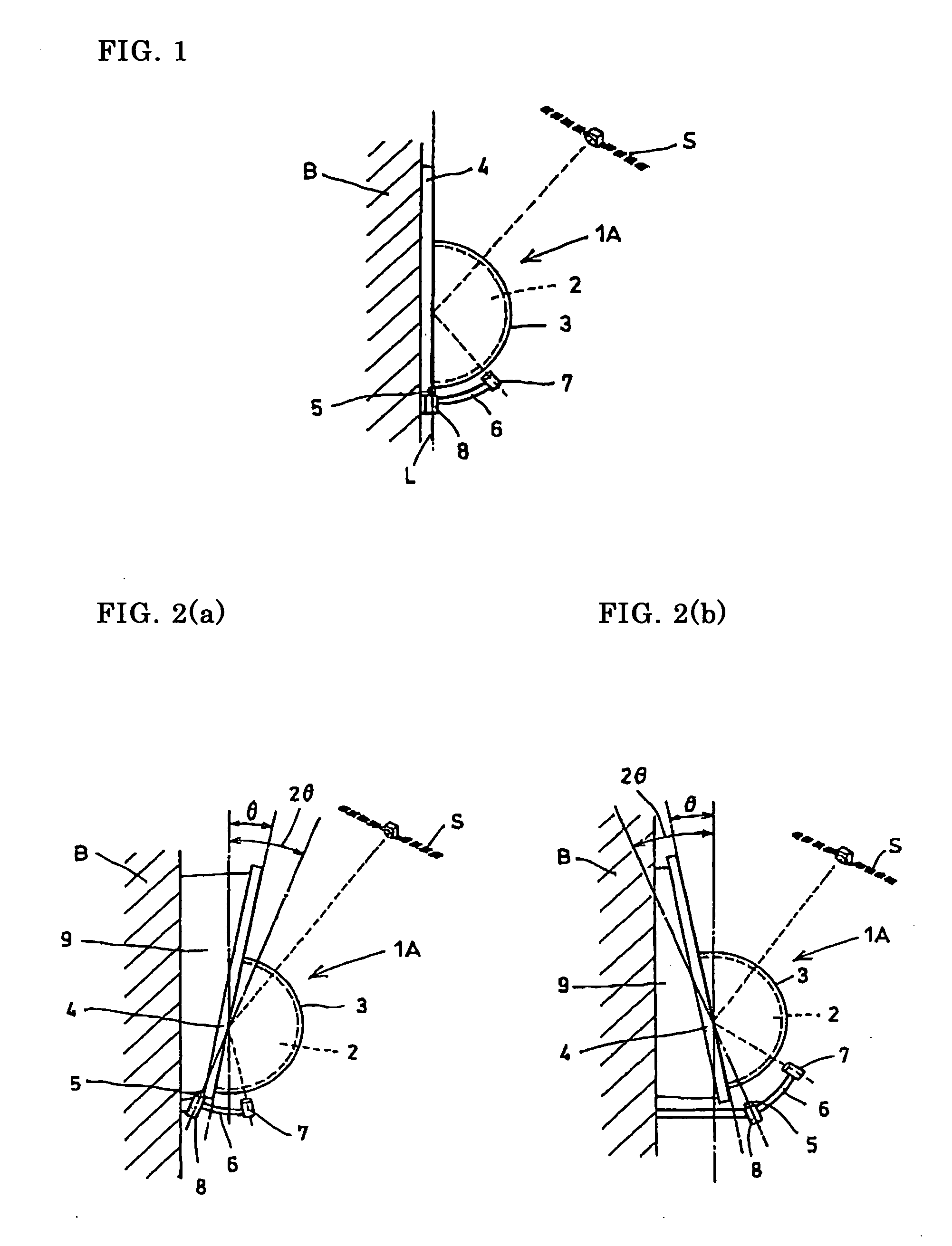
[0011] In this embodiment of the invention, the arm can be turned about an axis that is a perpendicular line passing the center of the lens, and while the primary feed held by the arm maintains its posture to face the center of the lens, such turn of the arm causes the primary feed to move on a semicircle centering the axis and on a plane that is perpendicular to the axis. Therefore, the adjustment of movement is needed with respect to only one axial direction, and accordingly the adjustment required during installation is easy as compared with parabolic antennas that need the combination of three axes and conventional lens antennas that require the positional adjustment of the primary feed by measuring the direction of wall every time and choosing the data suitable for the direction because the direction of the installation wall is obscure. Particularly, in the embodiment of the present invention, the positional adjustment is possible by simply adjusting the primary feed without making an adjustment of such a large parabolic antenna and a lens, etc.
[0018] The lens antenna equipment according to the composition of 4), which is a lens antenna system having a structure according to the above-described compositions (1) and (3) and using the arms of the compositions (1) and (3), exhibits the combined effects of the compositions (1) and (3). The lens antenna equipment according to the composition (4) is particularly effective for adjusting the positions of primary feeds to the respective focus position of a plurality of satellites, and makes it possible to easily perform positional adjustment of a plurality of primary feeds at once.
[0023] Moreover, the size of reflectors in the first, third, and fourth embodiments of the invention can also be decreased to the necessary minimum in combination with the fifth embodiment of the invention.
[0024] Also, in the case of the lens antenna equipment according to these embodiments, scenic incongruity can be minimized since it can be closely attached to a wall in a manner such that the reflector becomes assimilated to the wall and only the hemispherical lens protrudes from the wall. For example, it is possible to assimilate the whole antenna with the wall by adopting a design in which the surfaces of the lens and the reflector are provided with the same pattern as that of the installation surface or by using a transparent plastic reflector in which a reinforcement material such as a metallic mesh is buried.
[0025] Besides, electromagnetic interference due to a wind or the like will rarely be caused because the support of the antenna is accomplished directly with a wall and because a hemispherical lens is not so susceptible to wind pressure. Also, it is advantageous in terms of cost that there is no need to install a solid mast.

Problems solved by technology

Therefore, the setting of the parabolic antenna is very difficult because three axes of a vertical direction (elevation angle), a transverse direction (azimuth angle), and an inward direction of antenna face must be adjusted for its installation.
In addition, the parabolic antenna is inferior with respect to electrical and mechanical durability against a strong wind since a mast must support against the wind loading during a strong wind that blows against the dish face, and thereby it may occasionally suffer from electromagnetic interference because of bending of the mast.
Also, if a firm mast is to be installed, it is susceptible to problems in terms of cost and view and to installation regulations in Europe and America as well as in Japan.
However, the mechanism was yet to be further improved since its performance for positioning adjustment was unsatisfactory in the case of communication with a geostationary satellite, particularly in the case of a plurality of geostationary satellites.
However, it is not easy to judge them on the spot.
Thus, it takes time to achieve such adjustment.
Particularly, when it is necessary to make the adjustment corresponding to a plurality of geostationary satellites, it is difficult to accomplish the adjustment of the positioning because the respective positions of focus of the geostationary satellites must be searched for at the site since the direction of the wall or the like is obscure.

Method used


Image

  • Radiowave lens antenna device
  • Radiowave lens antenna device
  • Radiowave lens antenna device

Examples


first embodiment

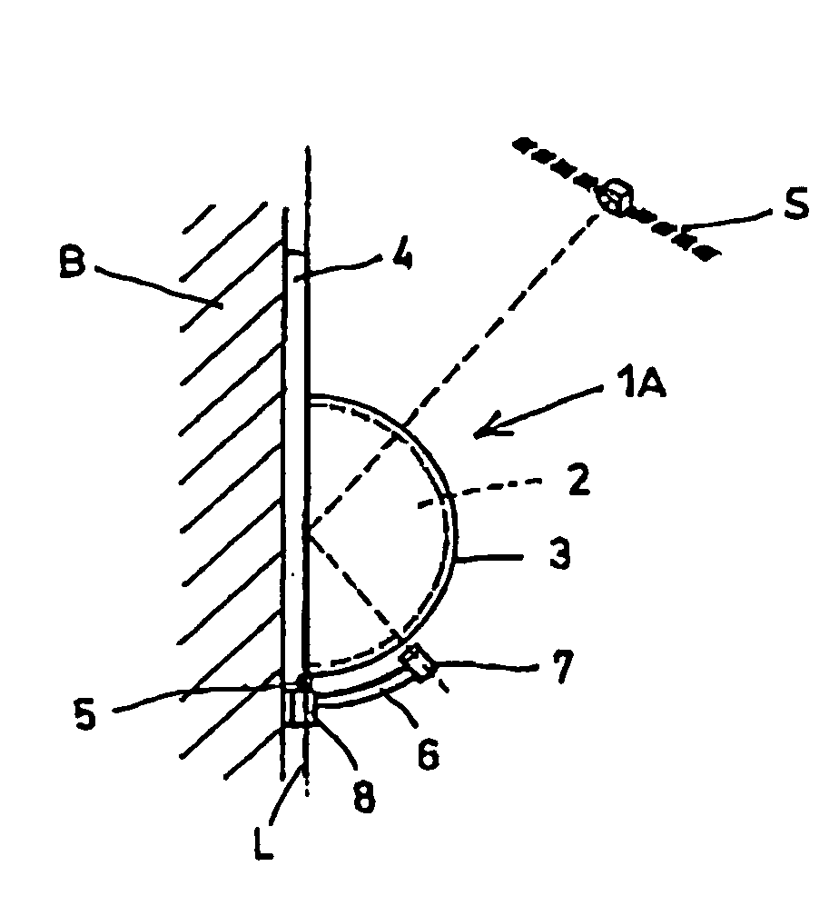
[0040]FIG. 1 shows an example of lens antenna equipment according to the The lens antenna equipment 1A comprises a hemispherical Luneberg lens 2 made of dielectric, a hemispherical cover 3 to protect the surface of the lens by covering it, a reflector 4 to be provided on a face equivalent to the cross-section made by halving a globular shape of the lens, an arm 6 supported by a fixing axis 5 assembled with the reflector 4, and a primary feed 7 held by the arm 6, all of which are unitarily assembled together.

[0041] The reflector 4 has a size larger than the diameter of the lens 2 so as to surely receive electromagnetic waves from counterpart equipment to be communicated with (in the figure, a geostationary satellite S). When the reflector 4 is attached to its installation position in a manner substantially perpendicular to the ground surface, the fixing axis 5, which is an axis about which the arm 6 turns, is located on a perpendicular line passing the center of the lens and takes a...

second embodiment

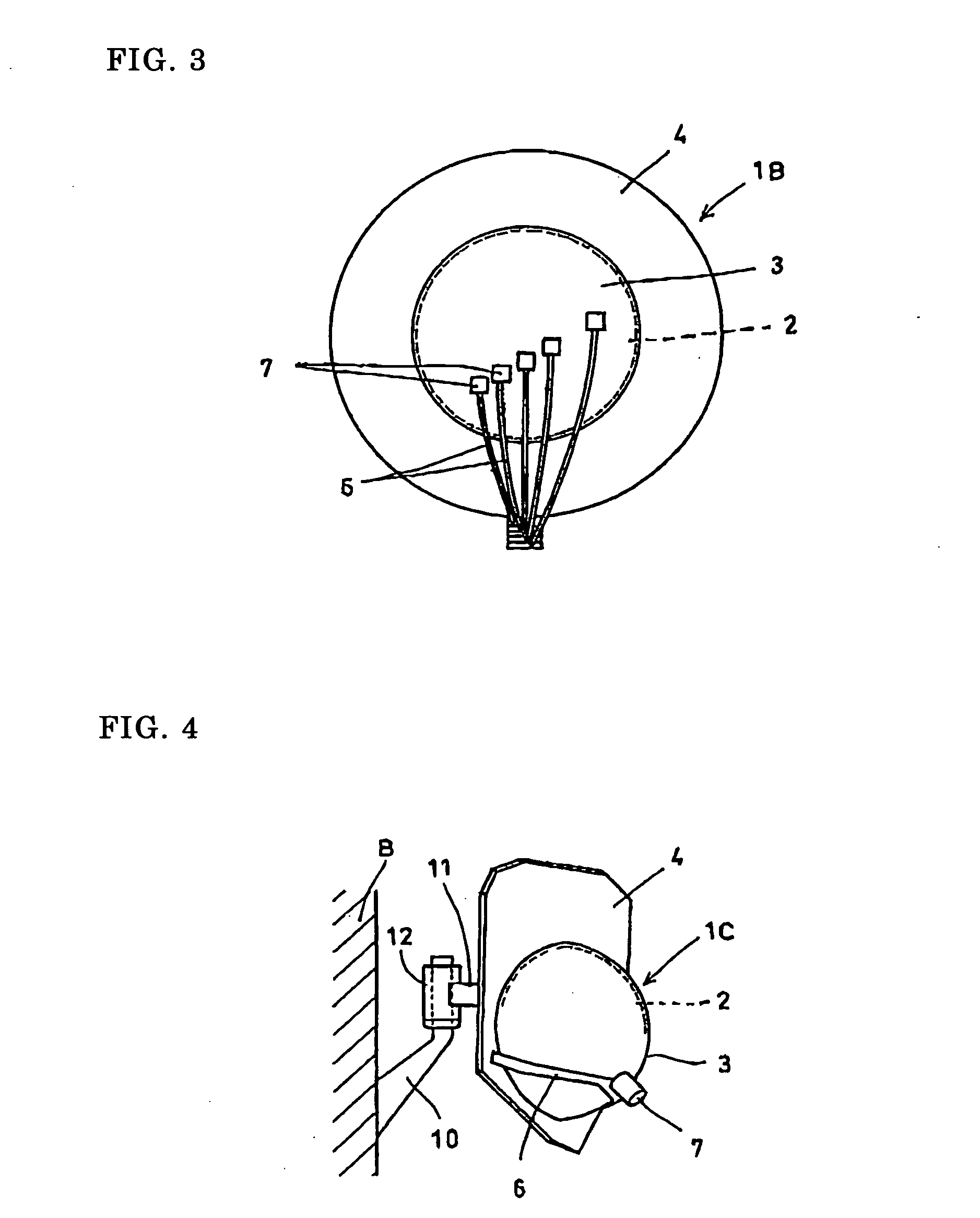
[0049]FIG. 4 shows an example of lens antenna equipment according to the In the lens antenna equipment 1C, a mast 10 to be fixed on wall B or the like is inserted in a sleeve 12 provided at the tip of a connection member 11 which is attached to the rear surface of a reflector 4, and the sleeve 12 is turnably engaged with the perpendicular axis part of the mast 10. An arm 6 for holding a primary feed 7 is structured such that its root portion is fixed to the reflector 4. The other composition is the same as the antenna equipment of FIG. 1. In the lens antenna equipment 1C of FIG. 4, the position of primary feed 7 is adjusted in advance to fit the geostationary satellite which is the counterpart equipment to be communicated with, and accordingly only adjustment needed at the installation site is to turn, relative to the mast 10, the whole antenna to the position where the receiving level of the electromagnetic wave becomes maximum. After the adjustment is completed, the sleeve 12 is ...

third embodiment

[0050] FIGS. 5(a) and 5(b) show an example of lens antenna equipment according to the In the lens antenna equipment 1D, a circular reflector 4 is used, and a circular orbit 13 which is concentric with a lens 2 is provided on the reflector 4. An arm 6 holding a primary feed 7 is formed into an arched shape to stride the lens 2, and both ends of the arm 6 are movably fixed to the circular orbit 13. The lens antenna equipment 1D of FIG. 5 is also structured such that the primary feed 7 can be moved by sliding it on the arm 6 in the arm's longitudinal direction. Thus, the primary feed 7 can be positioned to an optimum point by combining such two moving operations. The adjustment can easily be done if a line, which is to be afforded on the surface of the lens 2 and which is parallel to a plane perpendicular to the axis of the lens 2, is marked in advance on a cover 3 for covering the lens 2, and if the primary feed 7 on the arm 6 is moved, by turning the arm 6, to the target point (focu...


PUM


Abstract

Lens antenna equipment including a hemispherical Luneberg lens made of dielectric, a reflector which has a size larger than the lens diameter and which is to be provided on a face equivalent to a cross-section made by halving a globular shape of the lens, a primary feed to be arranged at a focus part of the lens, and an arm for holding the primary feed, all of which are unitarily assembled together, wherein the holder of the arm can be turned about an axis that is a perpendicular line passing the center of the lens when the reflector is attached to its installation position in a substantially perpendicular manner with respect to the ground surface, and wherein the primary feed can be moved along the surface of the lens, on a plane that is perpendicular to the axis passing the center of the lens, and on a semicircle centering the axis.

Description

TECHNICAL FIELD [0001] The present invention relates to lens antenna equipment having a Luneberg lens, which is used for receiving electromagnetic waves for broadcast and communication from geostationary satellites and fixed antennas on the ground or which is used for transmitting electromagnetic waves to such satellites and antennas. BACKGROUND ART [0002] Generally, parabolic antennas have been used for communication with geostationary satellites. Basically, however, a parabolic antenna is capable of corresponding to electromagnetic waves from only one direction. Therefore, the setting of the parabolic antenna is very difficult because three axes of a vertical direction (elevation angle), a transverse direction (azimuth angle), and an inward direction of antenna face must be adjusted for its installation. In addition, the parabolic antenna is inferior with respect to electrical and mechanical durability against a strong wind since a mast must support against the wind loading during...

Claims


Application Information

Patent Timeline
Patent Type & Authority Applications(United States)
IPC IPC(8): H01Q15/02H01Q15/08H01Q3/04H01Q3/08H01Q3/14H01Q3/26H01Q19/06
CPCH01Q3/04H01Q3/08H01Q19/062H01Q3/2658H01Q3/14
Inventor KURODA, MASATOSHIYOKOTA, MASAOKAMISE, YASUHIRO
Owner SUMITOMO ELECTRIC IND LTD
Why Eureka
Try Eureka