
Electronic element module and electronic device using the same

Active Publication Date: 2006-11-23
NYTELL SOFTWARE LLC
View PDF12 Cites 0 Cited by
  • Summary
  • Abstract
  • Description
  • Claims
  • Application Information

AI Technical Summary

Benefits of technology

[0010] Accordingly, the present invention is directed to provide an electronic element module with less noise and higher bonding strength among the electronic elements and the circuit board thereof.
[0011] The present invention is also directed to provide an electronic device with better reliability.
[0019] Accordingly, the electronic element module and the electronic device using the same of this invention have better endurance in shock and vibration, such that the reliability of the electronic element module and the electronic device can be improved.

Problems solved by technology

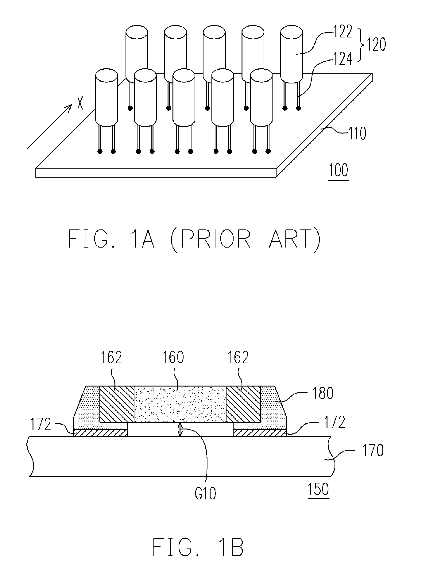
With the result, the electronic element module 100 fails to work.
However, this solution can't be used while the electronic elements 120 are arranged with high density.
Consequently, the gap G10 will make the noises during the operating of the surface mounted electronic element 160 be resonated and amplified, and the user will be discomfort.

Method used


Image

  • Electronic element module and electronic device using the same
  • Electronic element module and electronic device using the same
  • Electronic element module and electronic device using the same

Examples


Embodiment Construction

[0027] Reference will now be made in detail to the present preferred embodiments of the invention, examples of which are illustrated in the accompanying drawings. Wherever possible, the same reference numbers are used in the drawings and the description to refer to the same or like parts.

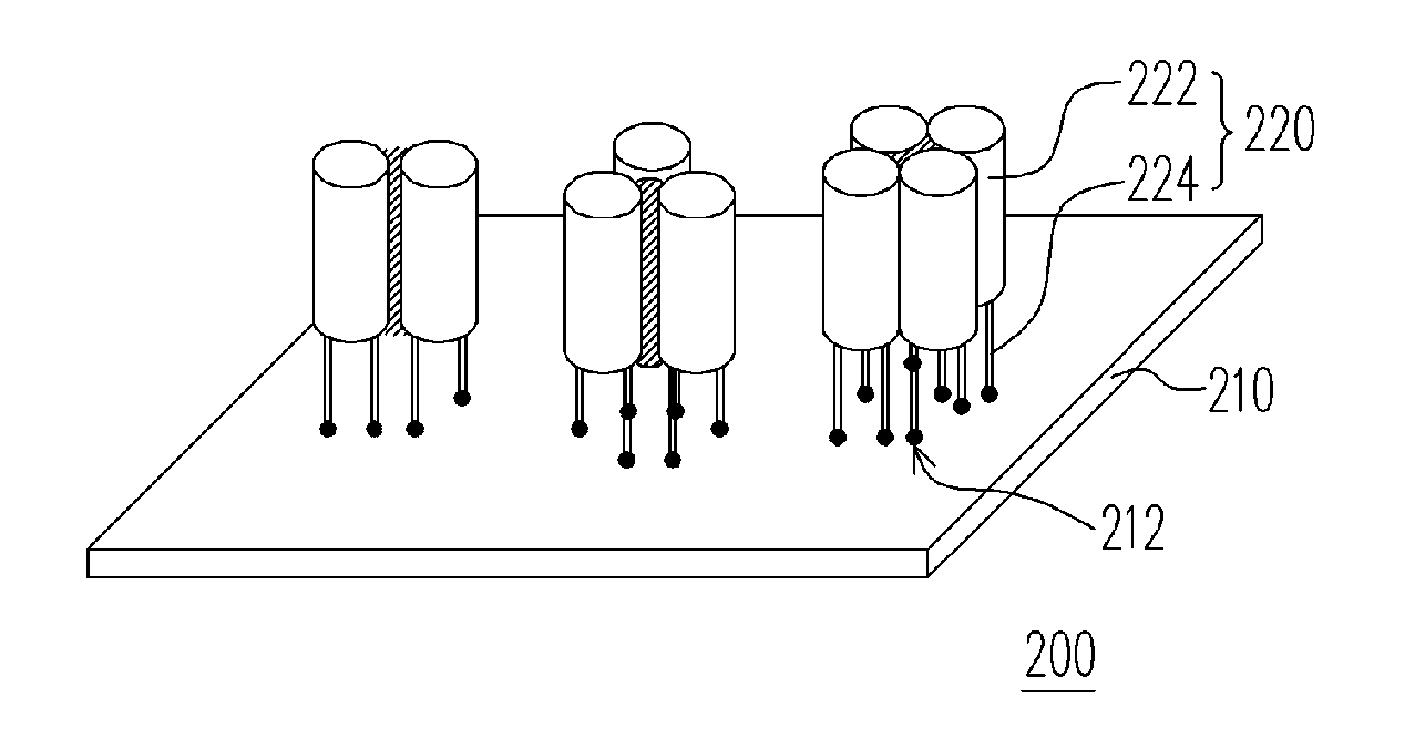
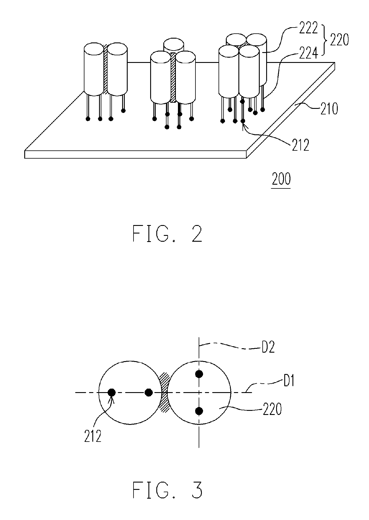
[0028]FIG. 2 is a schematic partial view showing an electronic element module according to an embodiment of the present invention. With reference to FIG. 2, the electronic element module 200 in this embodiment essentially comprises a circuit board 210 and a plurality of electronic elements 220. The circuit board 210 has a plurality of leg-holes 212. Each of the electronic elements 220 includes a body 222 and a plurality of legs 224 that connected to the body 222. In this embodiment, the number of the legs 224 in each of the electronic elements 220 is two, for example. But the number of the legs 224 in each of the electronic elements 220 could be three or more. Moreover, the bodies 222 of several of...


PUM


Abstract

An electronic element module and an electronic device using the same are provided. The electronic element module includes a circuit board and a plurality of electronic elements. In one embodiment, the circuit board has a plurality of leg-holes. Each of the electronic elements includes a body and a plurality of legs that connected to the body. Wherein, the bodies of the electronic elements are glued each other, and the legs of the electronic elements are partially plugged in the leg-holes. In another one embodiment, the circuit board has a plurality of contacts. The electronic element is disposed on the circuit board with a gap therebetween. The electronic element has a plurality of terminals that electrically connect to the contacts of the circuit board correspondingly. Otherwise, the gap is filled with glue.

Description

CROSS-REFERENCE TO RELATED APPLICATION [0001] This application claims the priority benefit of Taiwan application serial no. 94116052, filed on May 18, 2005. All disclosure of the Taiwan application is incorporated herein by reference. BACKGROUND OF THE INVENTION [0002] 1. Field of the Invention [0003] The present invention relates to an electronic element module and an electronic device using the same. More particularly, the present invention relates to an electronic element module with better strength and an electronic device using the same. [0004] 2. Description of the Related Art [0005] With the advancing by leaps and bounds of electronic technology, various kinds of electronic products have already been applied widely to our working and living, especially the electronic products, such as the most common information and electrical home appliances, etc. at present. In order to let these electronic products produce the special function, the electronic product nearly all has an elec...

Claims


Application Information

Patent Timeline
IPC IPC(8): H05K7/06
CPCH05K1/0271H05K1/18H05K3/305H05K3/3442H05K2201/09418H05K2201/2045H05K2201/10537H05K2201/10636H05K2201/10651H05K2201/10977H05K2201/10522Y02P70/50
Inventor YU, LIANG-MINGTSOU, CHIEN-LUNGLIN, HSIN-LILIU, YUMING
Owner NYTELL SOFTWARE LLC
Learn More