Adjustable metro handle capable of being telescopically straightened and fixed through centrifugal force

A centrifugal force, adjustable technology, applied in the special position of the vehicle, transportation and packaging, vehicle parts and other directions, can solve the problems of safety accidents, passengers are difficult to hold, passengers are not easy to stand firmly, etc., to increase the bearing capacity Range, good endurance, and the effect of increasing the scope of use

Inactive Publication Date: 2020-06-05
邓妹仔
View PDF0 Cites 0 Cited by
  • Summary
  • Abstract
  • Description
  • Claims
  • Application Information

AI Technical Summary

Problems solved by technology

[0002] The subway is currently an important public rail transit. The subway has a large passenger capacity, which greatly reduces the pressure on urban traffic. However, due to the large passenger capacity, it is impossible for all passengers to have seats, so most passengers have to stand. Now, rely on the poles and handles to stabilize the balance. The current handles are all of the same standard, and the height of the handles is also uniform, but the height of each passenger is different, so it is difficult for short passengers to grasp the handle. And the height of the pull rod is higher than the height of the handle. When the handle cannot be reached, it is not easy for passengers to stand firm and hold on firmly, and safety accidents may occur. Therefore, a handle that can be adjusted in length is urgently needed. Therefore, we propose a retractable variable Adjustable subway handles that are straight and fixed by centrifugal force solve the above problems

Method used


Image

  • Adjustable metro handle capable of being telescopically straightened and fixed through centrifugal force
  • Adjustable metro handle capable of being telescopically straightened and fixed through centrifugal force
  • Adjustable metro handle capable of being telescopically straightened and fixed through centrifugal force

Examples


Embodiment Construction

[0024] The following will clearly and completely describe the technical solutions in the embodiments of the present invention with reference to the accompanying drawings in the embodiments of the present invention. Obviously, the described embodiments are only some, not all, embodiments of the present invention. Based on the embodiments of the present invention, all other embodiments obtained by persons of ordinary skill in the art without making creative efforts belong to the protection scope of the present invention.

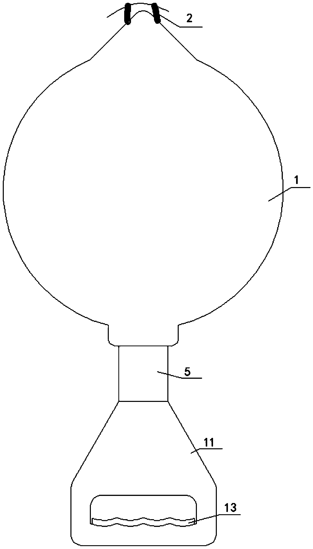
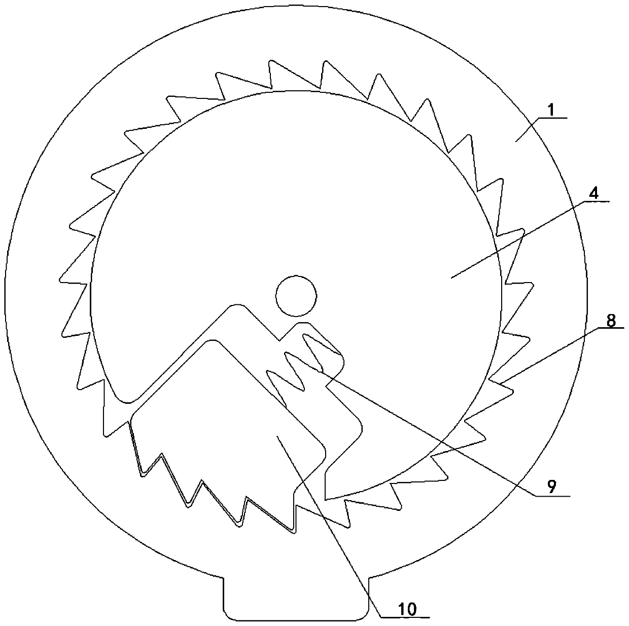
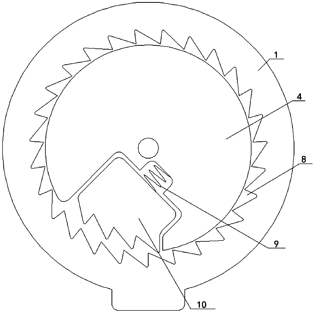
[0025] see Figure 1-10 , an adjustable subway handle that can be stretched and straightened and fixed by centrifugal force, comprising a shell 1, the shape of the shell 1 is disc-shaped and the material of the shell 1 is hard plastic material, the fixed rope 2 The material is nylon rope and the shape of the fixed rope 2 is an annular strip. The top of the housing 1 is movably connected with the fixed rope 2. The fixed rope 2 plays a role of fixing. The middle...


PUM


Abstract

The invention discloses an adjustable metro handle capable of being telescopically straightened and fixed through centrifugal force. The handle includes a housing, the top of the shell is movably connected with a fixing rope. A coil spring is fixedly connected to the middle of the shell, a rolling block is fixedly connected to the middle of the coil spring, a pull rope is fixedly connected to theouter side of the rolling block, a first spring is fixedly connected to the inner wall of the pull rope, a first ejector block sleeving the middle of the first spring is fixedly connected to the top of the first spring, tooth grooves are formed in the inner wall of the shell, and a second spring is fixedly connected to the rolling block. The invention discloses an adjustable subway handle capableof being telescopically straightened and fixed through centrifugal force. Through cooperative use of the clamping blocks and the tooth grooves, after the length of the pull rope is adjusted, the pullrope only needs to be pulled suddenly and quickly, the clamping blocks are thrown out through centrifugal force, the clamping blocks are clamped with the tooth grooves, and therefore the length of thepull rope is fixed, the effect of fixing the length of the pull rope is achieved, stress points are provided for passengers, and the passengers can stand stably and firmly.

Description

technical field [0001] The invention relates to the technical field of subway handles, in particular to an adjustable subway handle that can be stretched and straightened and fixed by centrifugal force. Background technique [0002] The subway is currently an important public rail transit. The subway has a large passenger capacity, which greatly reduces the pressure on urban traffic. However, due to the large passenger capacity, it is impossible for all passengers to have seats, so most passengers have to stand. Now, rely on the poles and handles to stabilize the balance. The current handles are all of the same standard, and the height of the handles is also uniform, but the height of each passenger is different, so it is difficult for short passengers to grasp the handle. And the height of the pull rod is higher than the height of the handle. When the handle cannot be reached, it is not easy for passengers to stand firm and hold on firmly, and safety accidents may occur. Th...

Claims


Application Information

Patent Timeline
IPC IPC(8): B60N3/02
CPCB60N3/02
Inventor 邓妹仔
Owner 邓妹仔
Why Eureka
Try Eureka