Method for cement bond evaluation in boreholes

a technology of cement bonding and tube casing, which is applied in seismology for waterlogging, processing detected response signals, instruments, etc., can solve problems such as loss of isolation from the casing, risk, and loss of isolation

Inactive Publication Date: 2006-11-23
SCHLUMBERGER TECH CORP
View PDF9 Cites 23 Cited by
  • Summary
  • Abstract
  • Description
  • Claims
  • Application Information

AI Technical Summary

Problems solved by technology

A common cause for loss of isolation from the casing is the presence of a channel in the casing, i.e., an angular section of the annulus that is filled by a liquid instead of cement.
Another cause for loss of isolation may be the presence of a microscopic annular space (microannulus) between Ie tube and the cement.
In both cases a risk occurs

Method used


Image

  • Method for cement bond evaluation in boreholes
  • Method for cement bond evaluation in boreholes
  • Method for cement bond evaluation in boreholes

Examples


Embodiment Construction

[0018] Same references will be used to reference same elements in the Figures throughout the description.

Measurement Set-Up

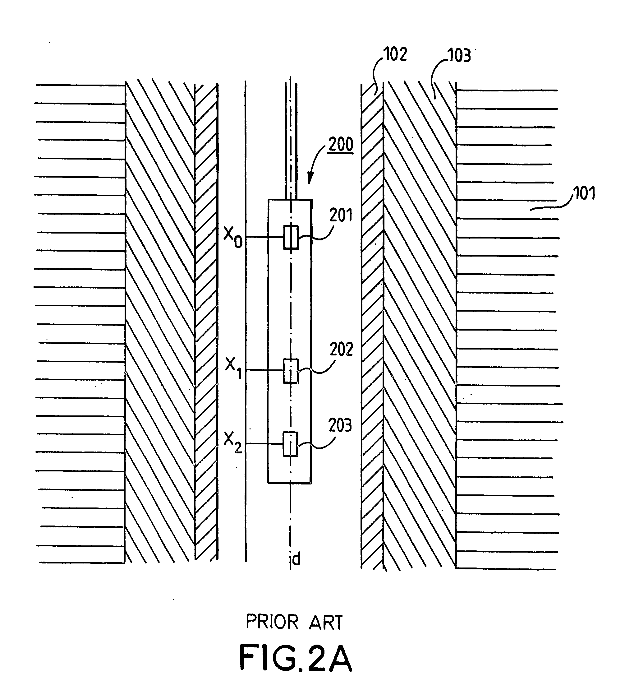
[0019]FIG. 2 contains a schematic representation of a Cement Bond Evaluating Device 200 (CBED) inserted in a borehole delimited by the tube 102 and the casing 103, formed in the formation 101. The CBED 200 comprises an Acoustic Signal Source (ASS) 201, located at a first location X0, and Acoustic Signal Receivers (ASR) 202 and 203 located respectively at a second location X1 and a third location X2.

[0020] As an example the ASS 201 may be a ceramic piezo-electrical transducer. The distances separating the ASS 201 from the ASR 202 and 203 may for example be respectively 90 cm and 150 cm. The ASS 201 emits acoustic pulses having a duration of 50 μs with a rate of 10 to 60 pulses per second. A typical main frequency of the acoustic signal may be 20 kHz. Other frequencies may be used in other examples.

[0021] Every pulse emitted by the ASS 201 generates a wavefro...


PUM


Abstract

A method for determining components of a tube casing surrounding a tube uses amplitude measurements of an acoustic signal wavefront emitted inside the tube. The acoustic signal wavefront is affected by the components of the tube casing while propagating in the tube. Various parameters such as an attenuation A(E) of the amplitude inside the tube and a coupling amplitude Eo may be determined. Theses parameters may be inserted in equations that are inverted to obtain a percentage of cement bonded φC in the tube casing, a percentage of cement de-bonded φD in the tube casing and a percentage of liquid φW in the tube casing.

Description

BACKGROUND OF THE INVENTION [0001] The invention generally relates to an apparatus and method for acoustically investigating a tube casing. [0002] One example of a tube casing is a wall of a borehole penetrating an earth formation. Such a wall may comprise an annular space filed with set cement. After the cement has set in the annular space of the casing it is common practice to use acoustic non-destructive testing methods to evaluate its integrity. This evaluation is of prime importance since the cement must guarantee zonal isolation between different formations in order to avoid flow of fluids from the formations (water, gas, oil) through the annular space of the casing. FIG. 1A contains an example of a vertical cross section of a borehole 100 in a formation 101. The borehole comprises at least one tube 102 that may for example be made out of steel. A casing 103 surrounds the tube 102 and provides an annular space ideally filled with cement. FIG. 1B illustrates a horizontal cross ...

Claims


Application Information

Patent Timeline
IPC IPC(8): G01V1/00G01N29/11G01N29/44G01N29/52G01V1/50
CPCG01N29/11G01N29/4472G01N29/52G01V1/50G01N2291/044G01N2291/103G01N2291/2636G01N2291/0231
Inventor SCHOEPF, VIRGINIEGUIBERT, KARINE
Owner SCHLUMBERGER TECH CORP
Why Eureka
Try Eureka