

Continuous extension of discrete transform for data processing
a discrete transformation and data processing technology, applied in the field of data processing, can solve the problems of reducing data bit size, interpolation, worst in quality,
- Summary
- Abstract
- Description
- Claims
- Application Information
AI Technical Summary
Benefits of technology
Problems solved by technology
Method used
Image

Examples
example of 2d
Image Zoom and Denoising
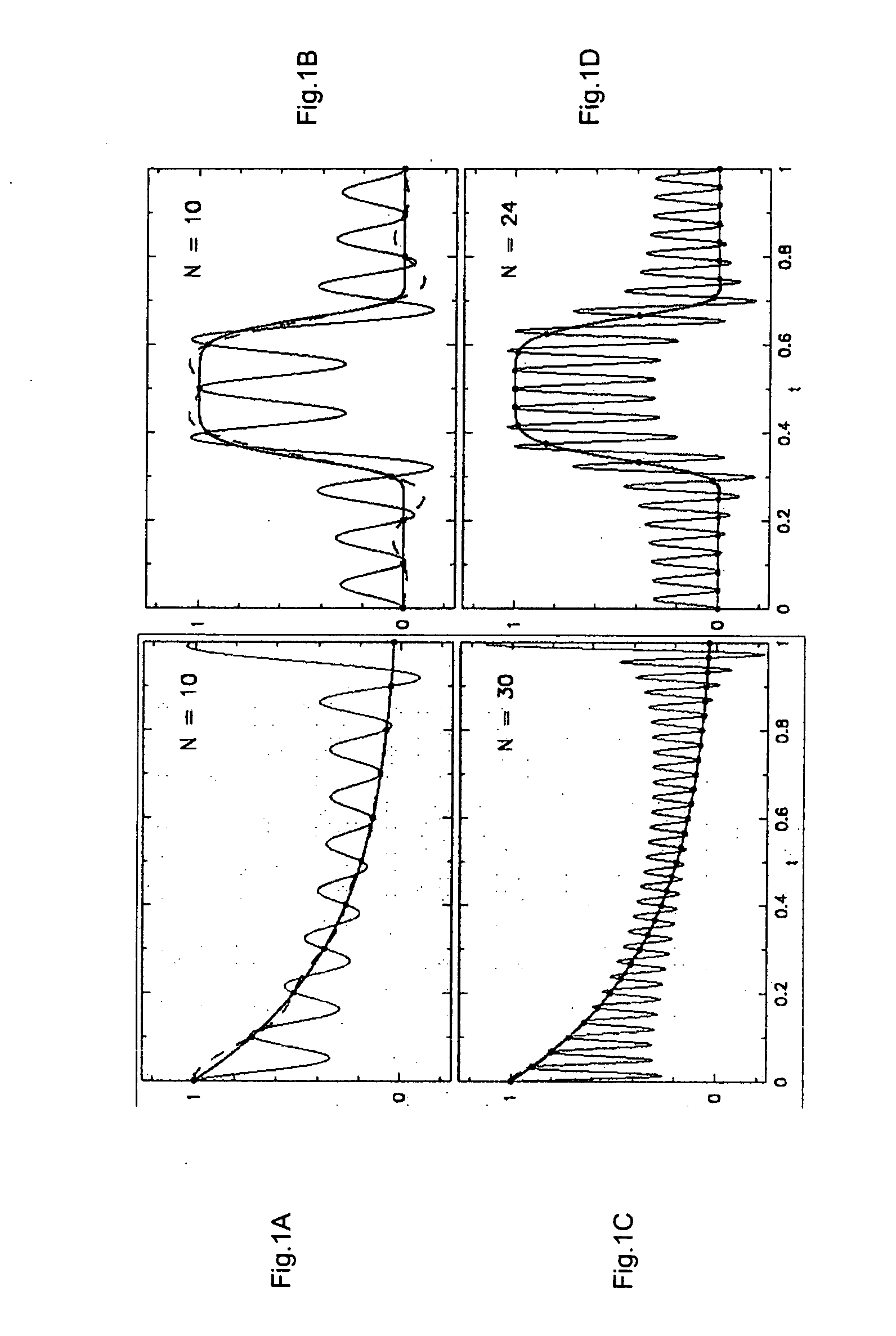
[0119]FIGS. 7a to 7c demonstrate that CEDOFT interpolation can be also effective for processing of noisy images. Here the 2-D CEDCT function is used to denoise an image taken by FLIR (“Forward Looking Infra-Red”) detector. Here in the truncated CEDCT function the high frequency modes corresponding to frequencies k>N / 4 have been simply discarded, whereas the maximum frequency in DCT along each of frequency axes is N / 2. This procedure has resulted in suppression of the “horizontal” noise intrinsic to FLIR detectors (see Ref.[8]), which has clearly improved the quality of the CEDCT-interpolated image. Further zooming into details of the processed image using CEDOFT could reveal additional details. It is important that the denoising is straightforward and fast, if one uses FFT-type algorithms for calculations of the DCT and CEDCT. It is also accompanied by significant compression of the factual image size, such as by a factor of 4 in FIG. 7C.
[0120] The reason fo...
examples
Impact of Larger Block Sizes
[0128] In FIGS. 12A to 12D, a 224×224 pixel-size fragment of the original 512×512 resolution test image “Bridge” (FIG. 12A) is shown that was interpolated by 2-D CEDCT to 448×448 pixel resolution image (FIG. 12B). FIG. 12C shows the image compressed to a compression factor C=35 by the method of thresholding quatization subdividing the original image dataset into blocks of size 33×33, overlapping in 1 pixel at the adjacent boundaries, and then using the truncated CEDCT to represent the compressed image with the same 448×448 resolution as in FIG. 12B. Note that overlapping of the adjacent blocks by at least one pixel is needed in the method of interpolation by CEDOFT generally in order to increase the resolution of the image also between the blocks. Otherwise the block effect would become apparent already in the uncompressed images. FIG. 12D shows the same fragment compressed to the same compression factor C=35, and interpolated by the truncated CEDCT to t...
example
Video Compression
[0137] Standard MPEG video compression algorithms combine 2D image compression, namely JPEG, with temporal interpolation techniques that are based on the assumption that a video sequence may contain images having portions that undergo no change at all, such as is the case with a fixed video camera and those portions relating to a fixed background, or portions that move within the 2D frame but otherwise are unchanged, such as is the case with a moving or panning video camera and those portions relating to distant fixed background. The video compression encoding provides for the portions of the image that does change frame by frame, such as a person talking or moving in the foreground. Essentially, a transform compression technique is used only within the 2D image, while coding and interpolation techniques are used to compress and reproduce the temporally unchanging portions, and this is combined with new data, typically compressed using a transform compression techn...
PUM
 Abstract
Description
Claims
Application Information