Image forming apparatus, cartridge, storage device and developer supplying method

Active Publication Date: 2006-11-23
CANON KK
View PDF3 Cites 22 Cited by
  • Summary
  • Abstract
  • Description
  • Claims
  • Application Information

AI Technical Summary

Benefits of technology

[0031] One aspect of the present invention is to provide an image forming apparatus that can reduce the number of image f

Problems solved by technology

When the video count is large, the amount of consumed toner is also large, and a large amount of toner must be supplied by driving the toner supply mechanism for an extended period of time.
However, there is a case wherein the following problems occur in the above described operation.
However, in a case wherein the durability of the developing apparatus is lowered and the parts are deteriorated, or wherein the electrostatic property of toner is degraded due to the environment, such as a high temperature and a high humidity, when a large amount of new toner is supplied to the developer container, all the toner can not be fully agitated and charged, so that image fogging or toner scattering will occur.
However, were a large amount of toner supplied

Method used


Image

  • Image forming apparatus, cartridge, storage device and developer supplying method
  • Image forming apparatus, cartridge, storage device and developer supplying method
  • Image forming apparatus, cartridge, storage device and developer supplying method

Examples


first exemplary embodiment

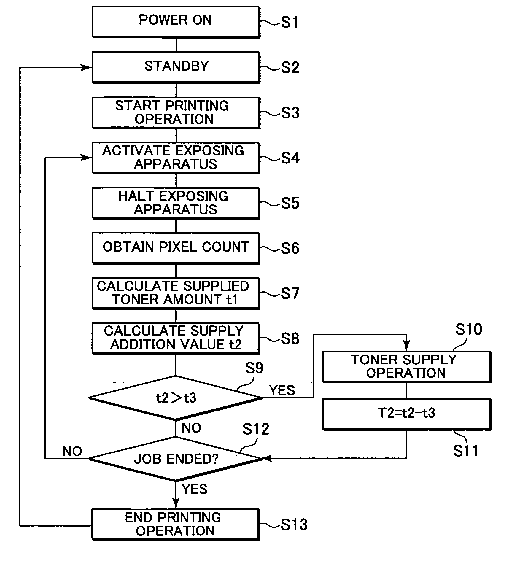
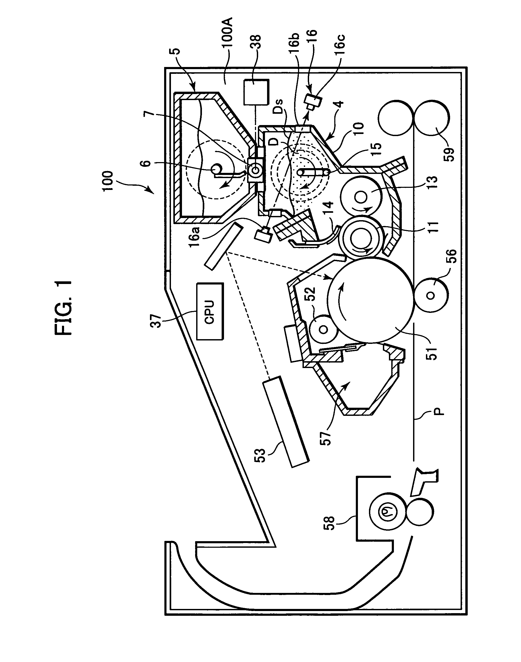
[0070]FIG. 1 is a schematic diagram showing an exemplary arrangement of an image forming apparatus according to a first embodiment of the present invention. Since an image forming apparatus 100 for this embodiment has a similar arrangement as the image forming apparatus 100 previously explained while referring to FIG. 18, the same reference numerals as are used in FIG. 18 are provided for members having the same structures and functions, and previously provided explanations will be quoted while detailed explanations are given for them.

[0071] That is, in this embodiment, the image forming apparatus 100 includes a drum shaped electrophotographic photosensitive member, which is an image bearing member that is rotatable in a direction indicated by an arrow, i.e., a photosensitive drum 51. When the image forming operation is started, an electrifier 52 uniformly charges the surface of the photosensitive drum 51, and an exposing apparatus 53, such as a laser irradiation apparatus, perform...

second exemplary embodiment

[0125] The feature of this embodiment is that the image forming process unit that includes at least a developing apparatus is integrally formed as a cartridge detachable to an image forming apparatus, and that a nonvolatile memory is provided as a storage unit for the cartridge, and information for an addition value t2 is stored in the nonvolatile memory. As needed, information for a supply threshold value t3 can also be stored in the nonvolatile memory of the cartridge.

[0126] Since the schematic configuration and the basic operation of the image forming apparatus in this embodiment are similar to those in the first embodiment, the explanation for the first embodiment will be summarized to avoid repetition of the description. The cartridge will now be described.

[0127]FIG. 5 is a schematic diagram showing an exemplary structure of a cartridge employed for this embodiment. In this embodiment, a cartridge 30 is provided by integrally forming a photosensitive drum 51, as explained in ...

third exemplary embodiment

[0137] The feature of a third embodiment is that the operation explained in the second embodiment is performed by a color image forming apparatus with a plurality of process cartridges, and that a supply threshold value t3 is also stored in nonvolatile memories of these process cartridges.

[0138]FIG. 9 is a diagram showing an example color image forming apparatus of tandem intermediate transferring type according to this embodiment. According to this embodiment, a main body 100A of an image forming apparatus 100, four image forming units, i.e., four image forming stations P (PY, PM, PC and PBk) are arranged in series in the image feeding direction. The image forming stations P (PY, PM, PC and PBk) include, respectively, electro-photographic photosensitive members in a drum shape, i.e., photosensitive drums 51 (51Y, 51M, 51C and 51Bk), which serve as image bearing members; electrifiers 52 (52Y, 52M, 52C and 52Bk), which are charging rollers serving as a charging units; exposing appar...


PUM


Abstract

An image forming apparatus is provided which includes a developing apparatus configured to form a developer image; a supply apparatus configured to supply developer to the developing apparatus; a detector configured to detect an amount of developer consumed during an image forming process; and a controller configured to perform an addition calculation for the amount of developer consumed, and for employing a value obtained by the addition calculation and a supply threshold value to determine whether developer should be supplied to the developing apparatus, wherein the controller sets the supply threshold value in accordance with an operating state of the developing apparatus.

Description

BACKGROUND OF THE INVENTION [0001] 1. Field of the Invention [0002] The present invention relates to an image forming apparatus, such as a copier or a page printer, that includes a developing apparatus that employs electro-photography, for example, to form a latent image on an image bearing member, that develops the latent image using a developer transporting member that supplies a developer to develop an image. The present invention also relates to a cartridge, a storage device and a developer supply method. [0003] 2. Description of the Related Art [0004] Conventionally, two-component developing apparatuses, which employ a two-component developer containing toner and a carrier, have been employed for image forming apparatuses. Recently, however, there has been increased use of one-component developing apparatuses, which employ developers, such as magnetic toner, having a single component and a simple composition. In addition, from the viewpoint that further improvements are desirab...

Claims


Application Information

Patent Timeline
IPC IPC(8): G03G15/08
CPCG03G15/0856G03G15/0889G03G15/0862
Inventor YAMAGUCHI, SEIJIIMAMURA, ISSEI
Owner CANON KK
Why Eureka
Try Eureka