Electric adapter organizer

a technology for organizing electrical adapters and adapters, which is applied in the direction of electrical apparatus casings/cabinets/drawers, coupling device connections, casings/cabinets/drawers, etc., can solve the problems of voiding manufacturer's warranties, affecting the actual use of electrical adapters, and affecting the use of rechargeable devices

Inactive Publication Date: 2006-11-23
YOUNG ERIC D
View PDF16 Cites 50 Cited by
  • Summary
  • Abstract
  • Description
  • Claims
  • Application Information

AI Technical Summary

Benefits of technology

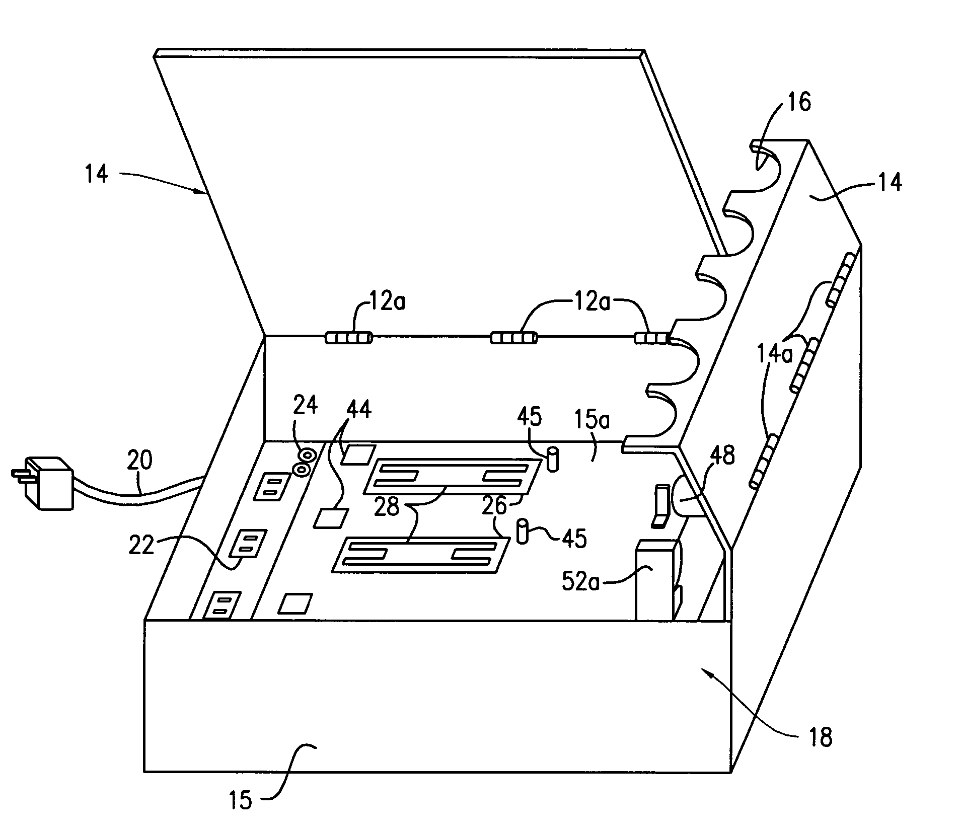
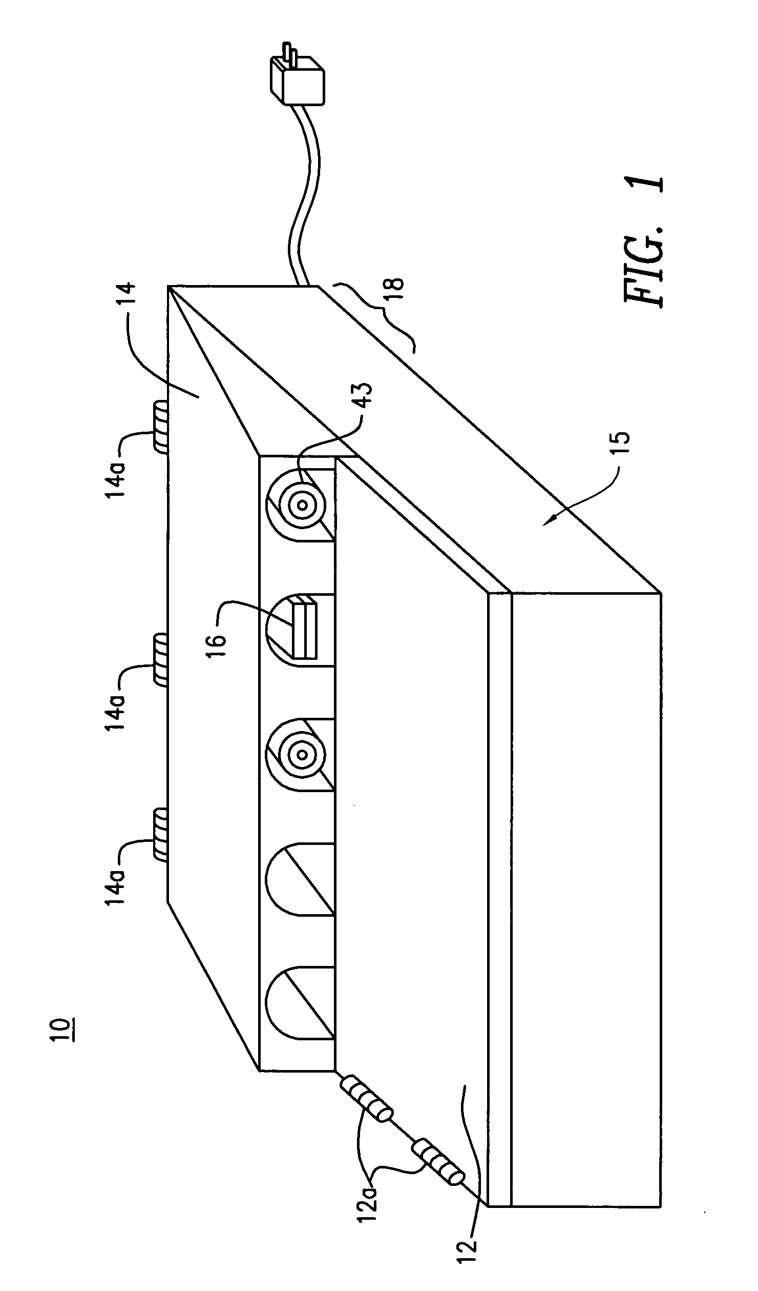
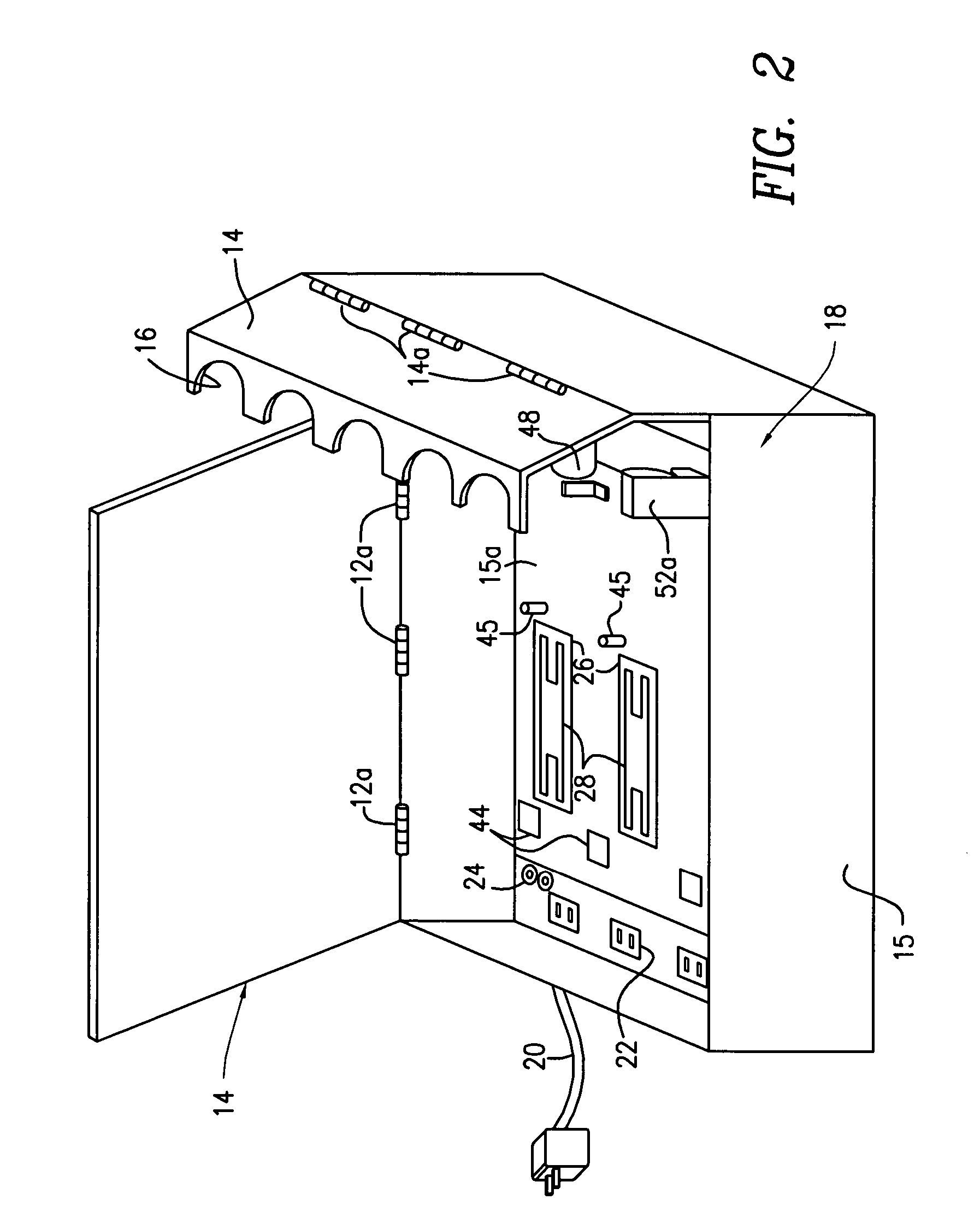
[0012] The present invention relates to a unit capable of storing one or more recharging adapters, such adapters in general being referred to hereinafter as “adapters,” incorporating high-voltage electrical outlets. The unit includes one or more spools to organize and contain excess adapter wire and a mechanism to permi

Problems solved by technology

The use of an improper adapter may damage the rechargeable device and may also void the manufacturer's warranties.
Moreover, to accommodate various potential placements of the adapter/rechargeable device combination, the wires used by the adapters tend to be quite long, often significantly in excess of that actually needed.
The existing options for storing these adapters is inadequate.
This, however, leads to the familiar “rat's-nest” of wires and plugs.
Moreover, manufacturer's often do not place identifying markers on the adapters, so this “organized” consumer must still tangle with the wires and struggle to identify the appropriate adapter for a particular device.
Additionally, with so many rechargeable devices, it may be difficult to locate a sufficient number of convenient electric wall outlets to permit the consumer to charge multiple devices simultaneously.
This situation can result in wires being strung throughout the home, with exposed wires lying in the open creating the potential that the rechargeable device will be damaged, for example if the wire is pulled and the device falls.
In addition, the situation may present a potentially dangerous electrical hazard.
However, the existing options, such as they are, typically only deal with one of the number of problems previously identified.
However, among other shortcomings, power strips do not solve the above-n

Method used


Image

  • Electric adapter organizer
  • Electric adapter organizer
  • Electric adapter organizer

Examples


second embodiment

[0052] In the second embodiment, as shown in FIG. 10, in lieu of the clip / string mechanism of the above-described embodiment, a set of pinch rollers 80 is employed to provide a force urging the connection end of the wire back towards the interior of the housing 15. The pinch rollers 80 are spring loaded and are shown in an open position. Once the wire is fed through the rollers, the rollers are brought together to contact the wire held therebetween. Due to the spring loaded nature of at least one of the pulley rollers, the force of manually extending the wire will rotate the rollers to load the spring mechanism, and the release of the wire permits the spring to recoil, thus turning the rollers in the opposite direction, to thereby retract, or “reel in” the wire that has been extended.

[0053] In this arrangement, the set of pinch rollers 80 preferably include a mechanism to permit the opposite sides of the set of pinch rollers to be separated creating an opening, as shown in FIG. 10, ...

first embodiment

[0055] In the above-described embodiments, spring driven mechanisms are used to provide the necessary force for urging the connection end 43 into the housing 15. However, the present invention is not limited to this embodiment and any know manner of providing this urging force may be used. For example, a motor may used instead of the spring mechanism 40 in the first embodiment to provide an urging force.

[0056] In addition to variations in the spring design, alternatives to the brake mechanism are contemplated as well. The arrangement of the brake mechanism described in FIGS. 1-9 is preferred because of its simplicity and effectiveness. However, other arrangements include the use of a ratchet lock at the spring end of the mechanism (e.g., the spring in a roll-down window shade), a cam type mechanism or a manually operated lock. In any event, the present invention is not limited to any of the illustrated embodiments.


PUM


Abstract

An organizer for organizing and storing one or more of adapters provided with rechargeable devices includes an AC power supply to provide access to electricity for the adapters to permit one or more of the adapters to operate simultaneously; a mechanism for storing excess adapter wiring; and a mechanism adapted to permit selectively extension or retraction of the wire of the adapter.

Description

FIELD OF THE INVENTION [0001] The present invention relates generally to the organization and storage of electrical adapters associated with electronic devices that operate on rechargeable batteries, such devices generally being referred to as “rechargeable devices.” The adapters function to transform high voltage AC electricity from a wall outlet to the lower voltage DC electricity and appropriate amperage necessary to operate and recharge the related rechargeable device. BACKGROUND OF THE INVENTION [0002] A wide and growing variety of electrical devices are designed to operate using rechargeable batteries, and operate and recharge their batteries by means of a connection to an adapter that converts high-voltage AC electricity available, for example, from a wall outlet in the home, into the low-voltage DC electricity and appropriate amperage necessary to operate and recharge these devices. Each of these devices is manufactured to precise specifications requiring specific voltages a...

Claims


Application Information

Patent Timeline
IPC IPC(8): H01R13/72
CPCH01R13/72H02G11/02H01R25/006
Inventor YOUNG, ERIC D.
Owner YOUNG ERIC D
Why Eureka
Try Eureka