Vent cover for a mask assembly

a mask and assembly technology, applied in the field of mask assembly, can solve the problems of mask wearer health risk, non-compliance with cpap therapy, significant noise, etc., and achieve the effect of convenient assembly and disassembly, and convenient cleaning

Inactive Publication Date: 2006-11-30
RESMED LTD
View PDF5 Cites 94 Cited by
  • Summary
  • Abstract
  • Description
  • Claims
  • Application Information

AI Technical Summary

Benefits of technology

[0014] Another aspect of the invention relates to a vent cover that is easily accessible for cleaning.
[0015] Another aspect of the invention relates to a vent cover that is easy to assemble and disassemble.

Problems solved by technology

The washout of gas through the vent to the atmosphere removes exhaled gases to prevent carbon dioxide build-up, and hence “rebreathing”, which represent a health risk to the mask wearer.
Noise is a significant issue in CPAP treatment for the patient and / or the patient's bed partner.
Excessive noise can lead to patients being non-compliant with the CPAP therapy.
One source of noise is the exhaust through the vent in the mask or conduit.
The flow of gas through the vent creates noise as it exits to and interacts with the atmosphere.
Noise can adversely affect patient and bed-partner comfort, depending on both the magnitude and quality of the noise.
Further, bi-level gas delivery regimes tend to generate more noise than do constant level gas delivery regimes.

Method used


Image

  • Vent cover for a mask assembly
  • Vent cover for a mask assembly
  • Vent cover for a mask assembly

Examples


first embodiment

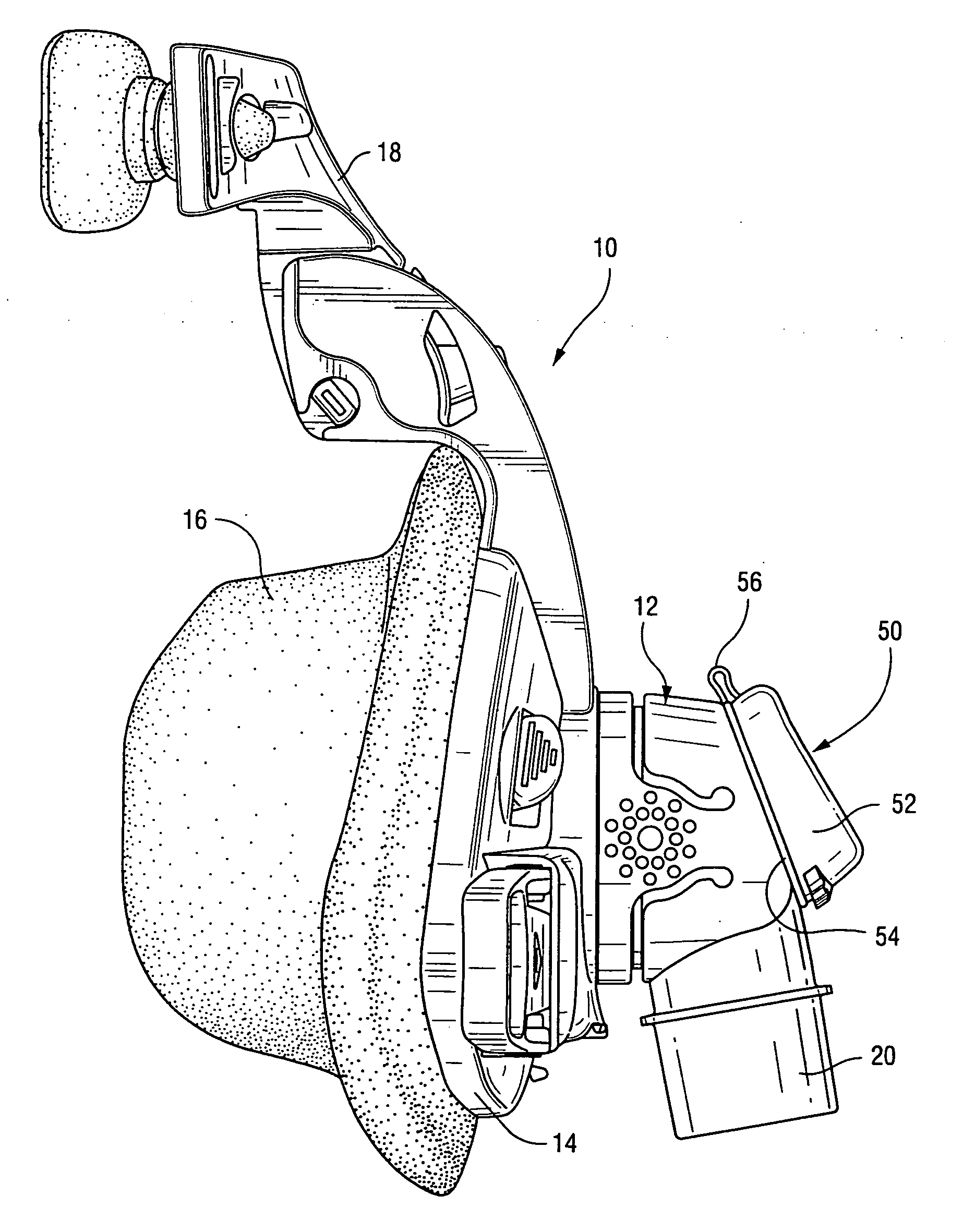
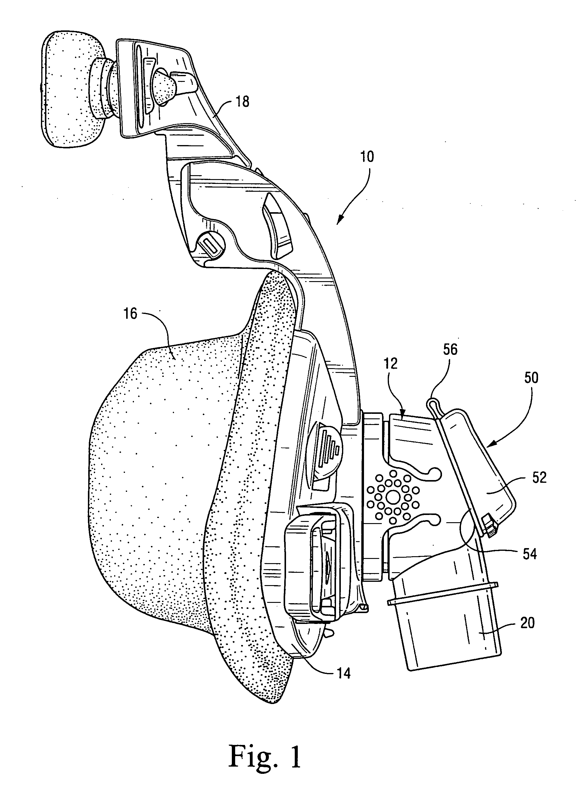
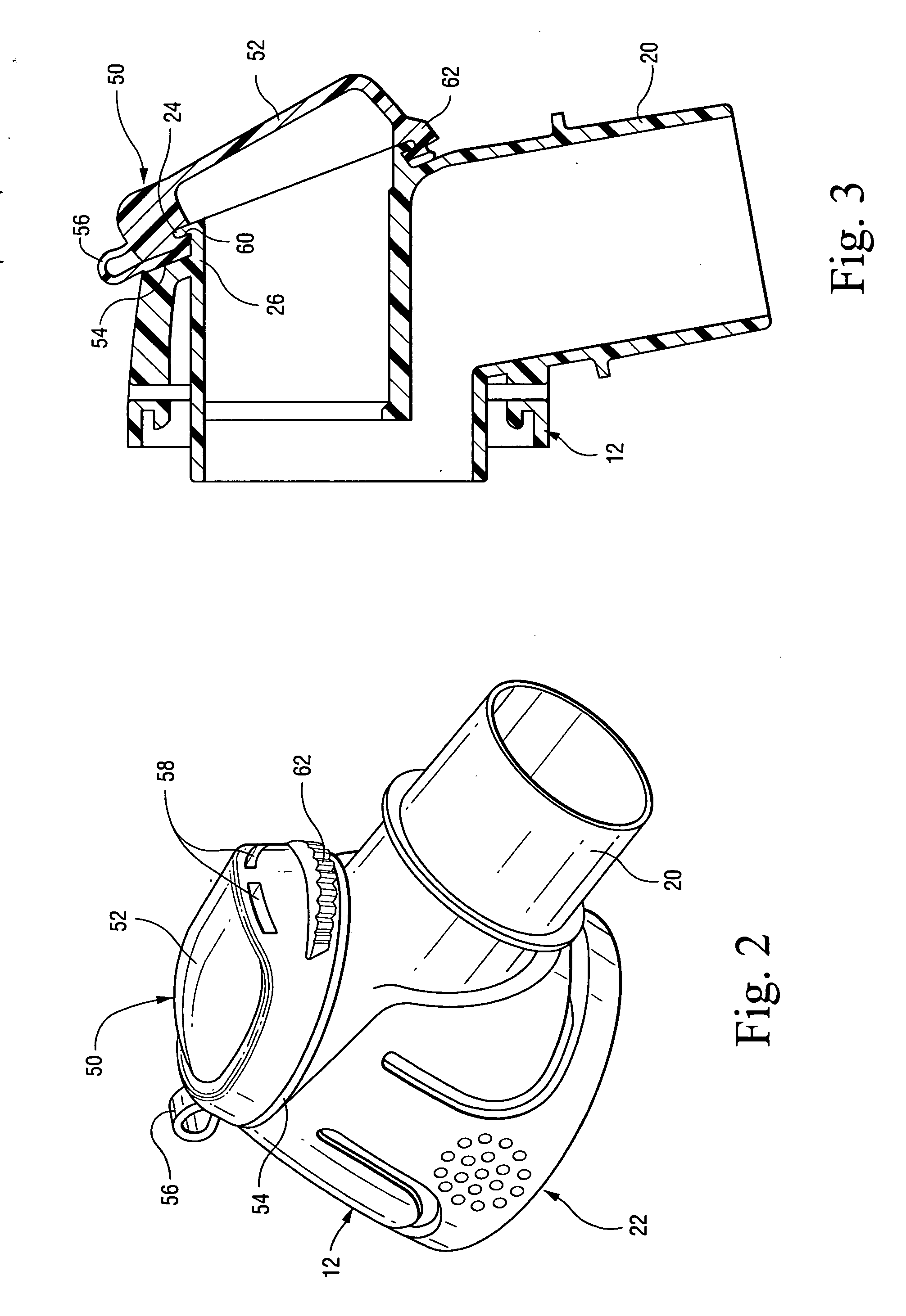
[0041]FIG. 1 illustrates a respiratory mask assembly 10 including a vent cover 50 constructed according to the present invention. The vent cover 50 is adapted to be removably connected to an elbow 12 of the mask assembly 10 with a snap-fit. The vent cover 50 is constructed from polypropylene or another material suitable for snap-fits, and provides a low cost, single molding alternative to silicone vents that are known in the art. In use, the vent cover 50 is structured to direct exhaust air from the mask assembly 10 in manner that minimizes noise and avoids disturbance of a bed partner.

Mask Assembly

[0042] As shown in FIG. 1, the respiratory mask assembly 10 includes a frame 14 having a front surface and a rear surface adapted in use to face the patient. A cushion 16 may be permanently or removably connected to the rear surface of the frame 14. A forehead support 18 is mounted to an upper portion of the frame 14. A headgear assembly (not shown) may be removably attached to the fram...

second embodiment

[0052]FIG. 6 illustrates a respiratory mask assembly 210 including a vent cover 250 constructed according to the present invention. The vent cover 250 is adapted to be removably connected to an elbow 12 of the mask assembly 210. The mask assembly 210 and swivel elbow 12 thereof are substantially similar to those described above and indicated with similar reference numerals. As noted above, the mask assembly 210 is merely exemplary, and the vent cover 250 may be adapted for use with other suitable mask assemblies.

[0053] As shown in FIGS. 6-10, the vent cover 250 is adapted to be removably connected to the flange 24 provided on the elbow 12 of the mask assembly 210. The vent cover 250 is positioned in covering relation with respect to the vent opening at the elbow outlet. Similar to the above, the vent cover 250 may be retro-fit to an existing elbow or fitted to a new elbow having a connection flange. As described below, the vent cover 250 is structured such that it may be easily asse...


PUM


Abstract

A respiratory mask assembly for delivering breathable gas to a patient includes a gas delivery path defining at least one vent outlet and a connection flange surrounding the vent outlet. A vent cover is removably connected to the connection flange such that the vent cover is positioned in covering relation with respect to the vent outlet. The vent cover includes a cap portion providing at least one vent aperture for gas washout and a ring-shaped retaining portion defining an aperture into which the connection flange is inserted. The cap portion is movably connected to the retaining portion to allow the cap portion to be attached to and detached from the connection flange while the retaining portion remains connected to the connection flange.

Description

CROSS-REFERENCE TO RELATED APPLICATIONS [0001] This application claims the benefit of U.S. Provisional Application No. 60 / 685,671, filed May 31, 2005, which is incorporated herein by reference in its entirety. [0002] Also, U.S. patent application Ser. No. 10 / 390,826, filed Mar. 19, 2003, and U.S. patent application Ser. No. 10 / 655,621, filed Sept. 5, 2003, are each incorporated herein by reference in its entirety.FIELD OF THE INVENTION [0003] The invention relates to a vent cover for use with a mask assembly for Non-invasive Positive Pressure Ventilation (NPPV) and for continuous positive airway pressure (CPAP) therapy of sleep disordered breathing (SDB) conditions such as obstructive sleep apnea (OSA). BACKGROUND OF THE INVENTION [0004] Treatment of sleep disordered breathing (SDB), such as obstructive sleep apnea (OSA), by continuous positive airway pressure (CPAP) flow generator systems involves the continuous delivery of air (or other breathable gas) pressurized above atmospheri...

Claims


Application Information

Patent Timeline
Patent Type & Authority Applications(United States)
IPC IPC(8): A62B9/04A61M16/00A62B18/02
CPCA61M16/0463A61M16/06A61M16/08A61M16/0638A61M2205/42A62B9/04A61M16/0816A61M16/065A61M16/0825
Inventor STALLARD, PHILIP THOMAS
Owner RESMED LTD
Why Eureka
Try Eureka