Pipe coupling

a technology of coupling and pipe, applied in the direction of sleeve/socket joint, fluid pressure sealed joint, joints with sealing surfaces, etc., can solve the problems of difficult fitting of couplings and harsh underground environment, and achieve the effect of effective connection and easy fitting

Inactive Publication Date: 2006-11-30
WRIGHT JOHN PETER
View PDF6 Cites 24 Cited by
  • Summary
  • Abstract
  • Description
  • Claims
  • Application Information

AI Technical Summary

Benefits of technology

[0005] It is an object of this invention to provide a pipe coupling that is relatively easy to fit and that provides an effective connection between plastics pipes having smooth cylindrical ends.

Problems solved by technology

It can be difficult to fit a coupling in these circumstances.
Along with high working pressures, the underground environment is also harsh and requires a coupling of robust construction.

Method used


Image

  • Pipe coupling
  • Pipe coupling
  • Pipe coupling

Examples


Embodiment Construction

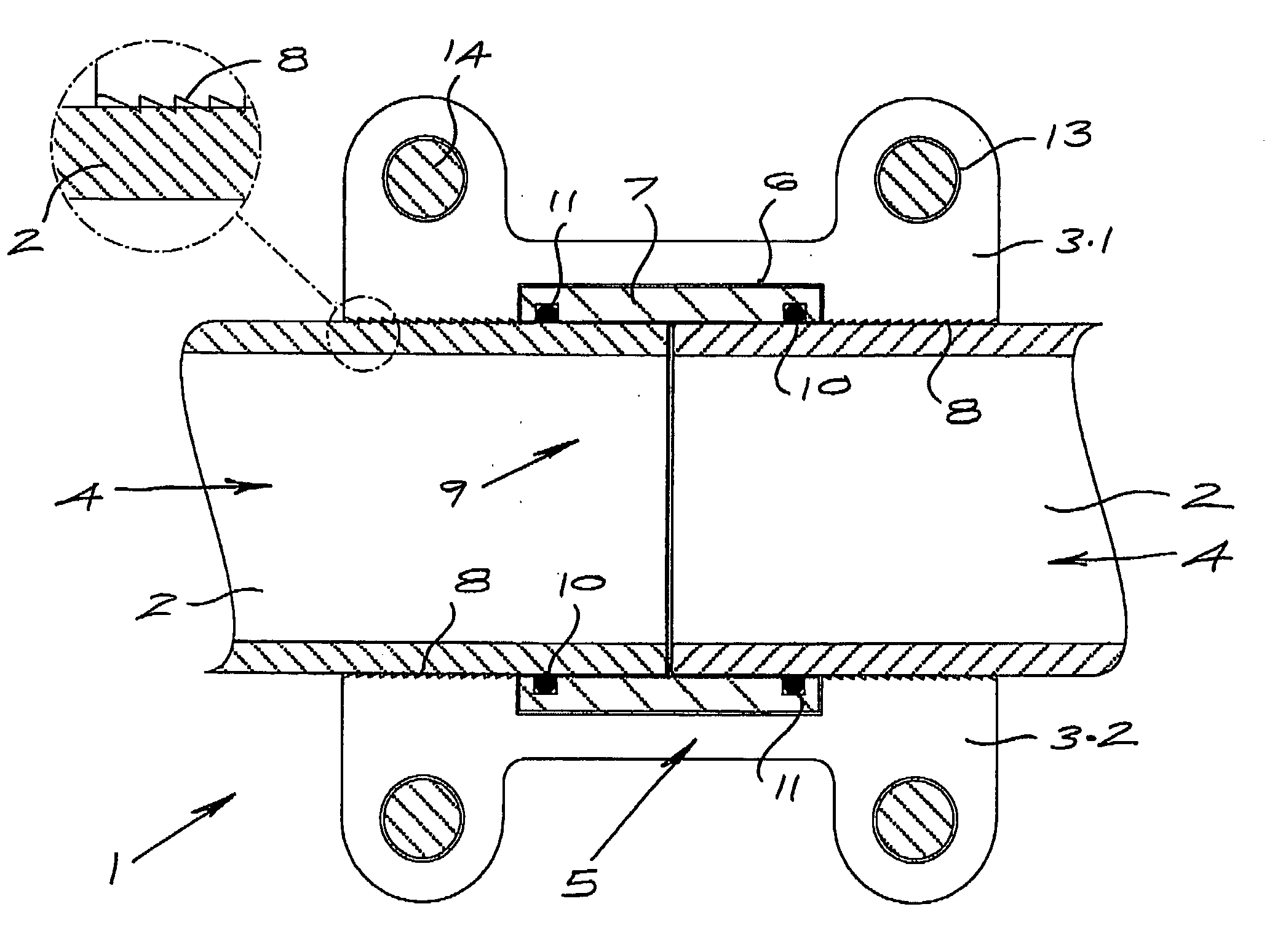
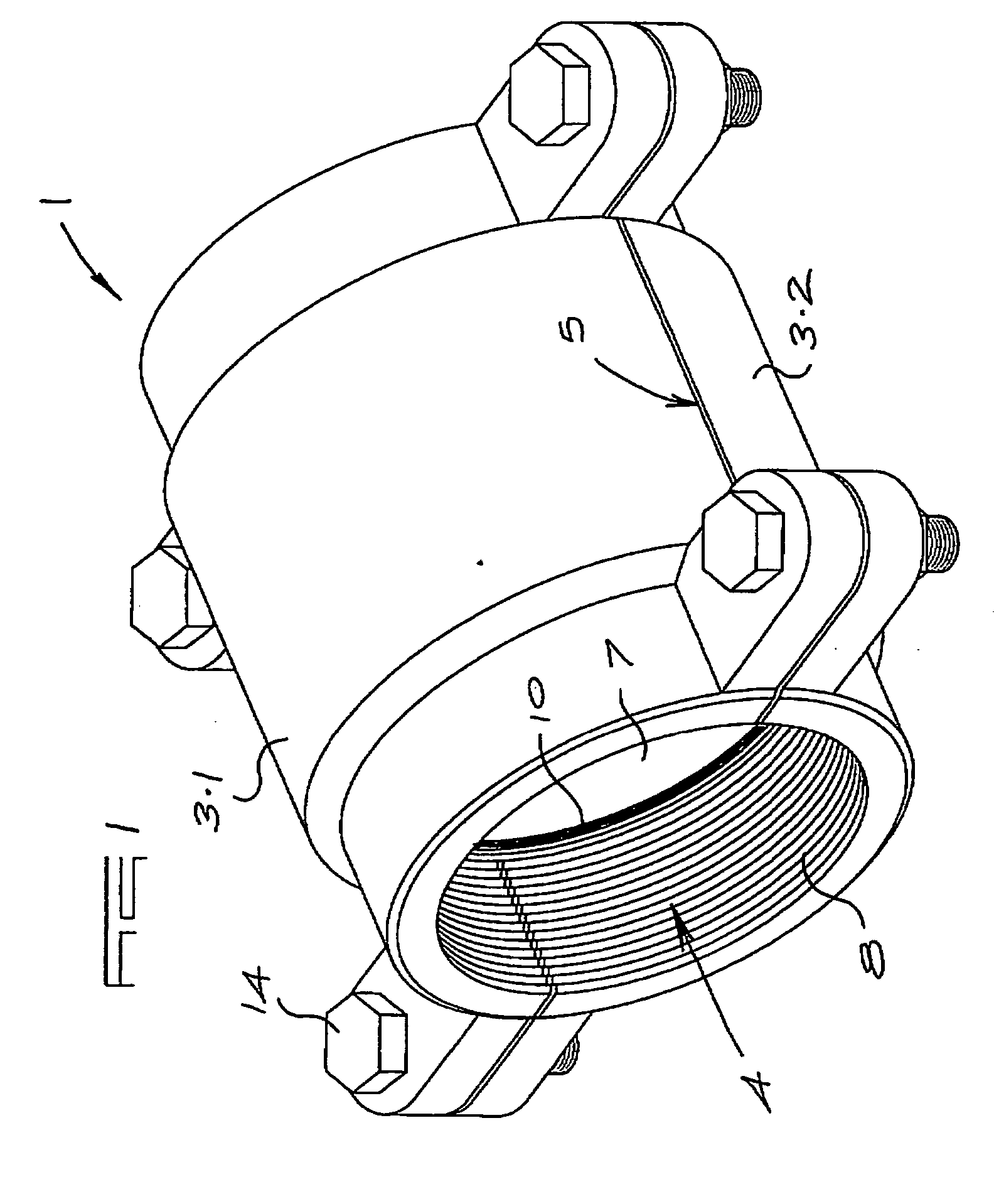
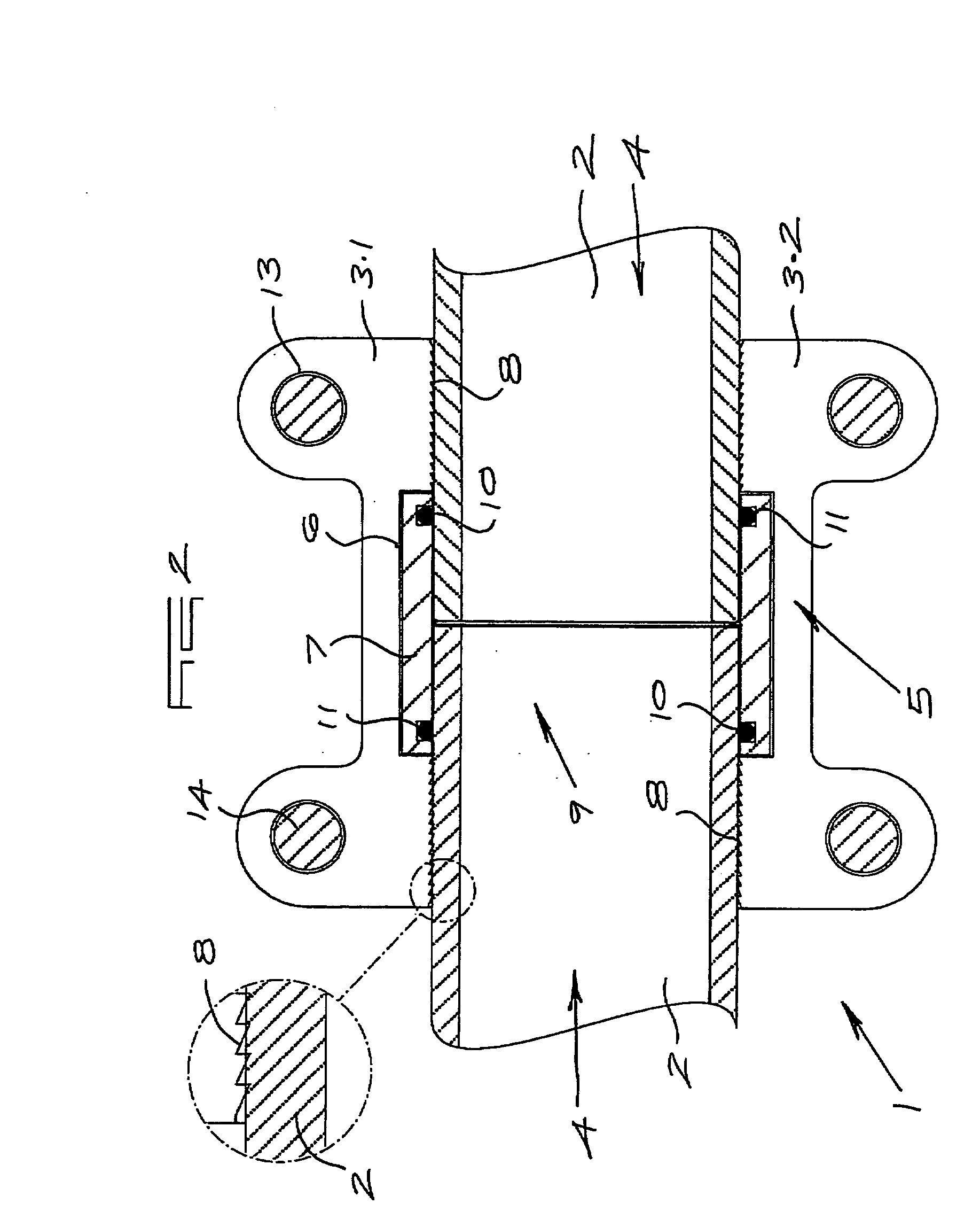
[0014] Referring to FIGS. 1 to 3, a pipe coupling (1) in accordance with this invention for connecting the ends of a pair of adjacent aligned pipes (2) is shown. The pipes are plastics and of the rigid kind having smooth cylindrical ends.

[0015] The coupling (1) includes a harness (3) with a longitudinal passage (4) extending therethrough. The harness (3) is split at (5) along its length to provide two cooperating halves (3.1) and (3.2). Located centrally in the length of the passage (4) is an annular recess (6). The recess (6) houses a rigid coupling sleeve (7). Pipe engaging teeth (8) are provided in the passage (4) to either side of the recess (6).

[0016] The sleeve (7) has a bore (9) with spaced apart internal ring seals (10) secured therein. The ring seals are shown as a pair of O-rings (10). Each of these 0-rings (10) is located in an annular groove (11) adjacent the open ends of the sleeve (7). The inner portions of the O-rings protrude into the bore (9) as required for seali...


PUM


Abstract

The invention relates to a pipe coupling for rigid plastics pipes having smooth cylindrical ends. The coupling includes a rigid sleeve having a longitudinal bore. Two spaced apart annular grooves are provided in the bore to respectively house deformable annular seals adjacent the ends of the sleeve. O-rings will be used as seals. A harness is securable over the sleeve with pipe engaging teeth adjacent each of the opposite ends. The harness is split longitudinally with a cylindrical passage having an annular recess to receive the sleeve. The teeth are formed by serrated ridges, preferably screw threads, in the passage extending from the recess to the outer ends of the passage. Corresponding lateral lugs on each half of the harness have bolt holes for assembly of the harness over the sleeve. The coupling is particularly suited for connecting plastics pipes used to convey backfill, normally in underground mining operations.

Description

FIELD OF THE INVENTION [0001] The invention relates to a pipe coupling and more particularly to a coupling for connecting rigid plastics pipes having a smooth cylindrical configuration and which are used in relatively high pressure applications. BACKGROUND OF THE INVENTION [0002] Pipe lines are used in a number of applications, usually for conveying liquids or suspensions of particulate material. The latter is often the case in mining operations, normally underground. In fact, plastics pipes have proved successful for use in conveying backfill in the mining industry. [0003] The lines are generally provided by connecting a series of pipes which are manufactured in lengths. The connecting couplings used must in some applications be able to withstand relatively high working pressures. This can be up to 110 bar and sometimes even more. [0004] Working on pipe lines in underground mines must often take place under low light conditions and in confined spaces. It can be difficult to fit a c...

Claims


Application Information

Patent Timeline
Patent Type & Authority Applications(United States)
IPC IPC(8): F16L21/06
CPCF16L17/04F16L21/08F16L21/005
Inventor WRIGHT, JOHN PETER
Owner WRIGHT JOHN PETER
Why Eureka
Try Eureka