Eureka AIR delivers breakthrough ideas for toughest innovation challenges, trusted by R&D personnel around the world.

Video synchronization signal removal circuitry

Active Publication Date: 2006-11-30
NAT SEMICON CORP
View PDF9 Cites 0 Cited by
  • Summary
  • Abstract
  • Description
  • Claims
  • Application Information

AI Technical Summary

Benefits of technology

[0005] In accordance with one embodiment of the presently claimed invention, video synchronization signal removal circuitry includes reference, output and video signal electrodes, control circuitry and signal routing circuitry. A reference electrode conveys a reference signal corresponding to a black video level. One or more output electrodes convey one or more output signals. One or more video signal electrodes convey one or more video signals, at least one of which includes a synchronization signal component having, between at least leading and trailing signal transitions, one or more signal values substantially unequal to the black video level. The control circuitry is coupled to at least one of the one or more video signal electrodes and responsive to the synchronization signal component by providing a control signal having assertion and de-assertion states, wherein the control signal is provided in the assertion state in response to an earlier portion of the synchronization signal component leading signal transition transcending a first threshold, following which the control signal: remains in the assertion state for a predetermined time interval in response to a later portion of the leading synchronization signal component signal transition transcending a second threshold beyond the first threshold, wherein the predetermined time interval is initiated by the later portion of the leading synchronization signal component signal transition transcending the second threshold and is terminated following a last one of the synchronization signal component leading and trailing signal transitions; and is provided in the de-assertion state in response to the later portion of the leading synchronization signal component signal transition failing to transcend the second threshold. The signal routing circuitry is coupled to the reference electrode, the one or more output electrodes, the one or more video signal electrodes and the control circuitry, and responsive to the control signal by conveying, as the one or more output signals, the reference signal substantially during the control signal assertion state and conveying the one or more video signals otherwise.
[0006] In accordance with another embodiment of the presently claime

Problems solved by technology

However, the tri-level synchronization signal used in high definition television (HDTV) analog component video signals (FIG. 1B) tends to be problematic since such technique cannot remove the synchronization tips completely, thereby often resulting in undesired residual signal components related to the original synchronization signal tips.

Method used


Image

  • Video synchronization signal removal circuitry
  • Video synchronization signal removal circuitry
  • Video synchronization signal removal circuitry

Examples


Embodiment Construction

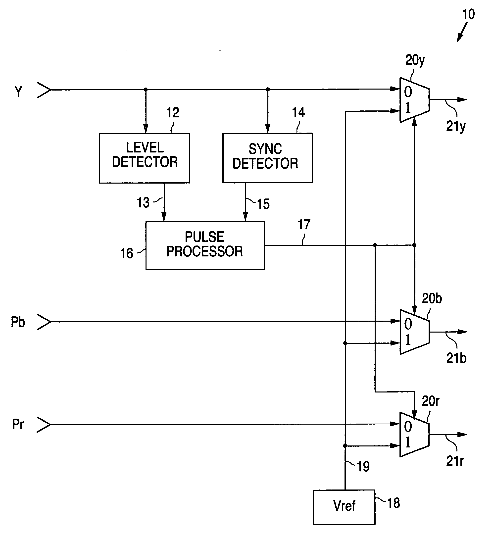
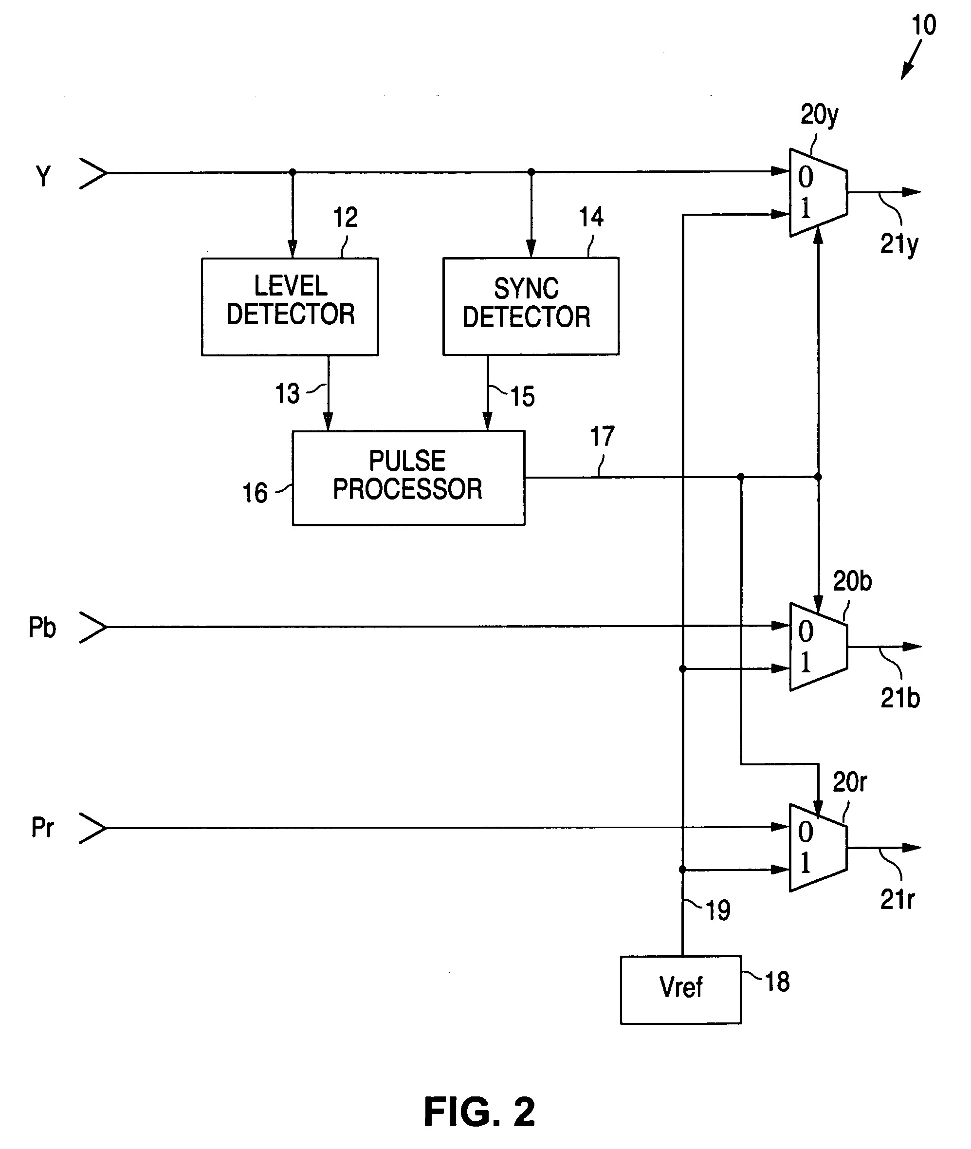
[0018] The following detailed description is of example embodiments of the presently claimed invention with references to the accompanying drawings. Such description is intended to be illustrative and not limiting with respect to the scope of the present invention. Such embodiments are described in sufficient detail to enable one of ordinary skill in the art to practice the subject invention, and it will be understood that other embodiments may be practiced with some variations without departing from the spirit or scope of the subject invention.

[0019] Throughout the present disclosure, absent a clear indication to the contrary from the context, it will be understood that individual circuit elements as described may be singular or plural in number. For example, the terms “circuit” and “circuitry” may include either a single component or a plurality of components, which are either active and / or passive and are connected or otherwise coupled together (e.g., as one or more integrated c...


PUM


Abstract

A video synchronization signal removal circuit in which a synchronization signal component of an incoming video signal is detected whereupon a reference signal corresponding to a black video level is substituted substantially during the synchronization signal interval.

Description

BACKGROUND OF THE INVENTION [0001] The present invention relates to circuitry for processing component video signals, and in particular, to circuitry for removing synchronization signals from component video signals. [0002] As is well-known, computer monitors and, increasingly, many higher quality televisions, receive their display signals in the form of component video signals such as GBR (green, blue, red), YPbPr (luminance, blue difference, red difference). Typically, the first of the three channels (e.g., the green and luminance signals) contains a composite signal in which both the video (green or luminance) and synchronization (horizontal and vertical) components are included. As is also well-known, the Consumer Electronics Association (CEA) standards (e.g., CEA-770.1-C, CEA-770.2-C and CEA-770.3-C) for component video signals specify the component video signal also containing the synchronization component to be a one-volt peak-to-peak signal, with the one extreme signal peak ...

Claims


Application Information

Patent Timeline
IPC IPC(8): H04N5/08
CPCH04N5/08
Inventor CHEN, DONGWEI
Owner NAT SEMICON CORP
Why Eureka
Eureka Blog
Learn More