
Three-dimensional imaging system and method for calculating correlation flight time by means of sparse aperture compression

A sparse aperture and time-of-flight technology, applied in radio wave measurement systems, electromagnetic wave re-radiation, instruments, etc., can solve the problem of inability to balance the accuracy of spatial resolution and depth information

Active Publication Date: 2013-12-25
NAT SPACE SCI CENT CAS
View PDF6 Cites 33 Cited by
  • Summary
  • Abstract
  • Description
  • Claims
  • Application Information

AI Technical Summary

Problems solved by technology

[0004] The purpose of the present invention is to overcome the defect that the spatial resolution and depth information accuracy of the 3D imaging system in the prior art cannot be balanced, thereby providing an efficient and easy-to-use 3D imaging system and method for calculating associated time-of-flight with sparse aperture compression

Method used


Image

  • Three-dimensional imaging system and method for calculating correlation flight time by means of sparse aperture compression
  • Three-dimensional imaging system and method for calculating correlation flight time by means of sparse aperture compression
  • Three-dimensional imaging system and method for calculating correlation flight time by means of sparse aperture compression

Examples


Embodiment Construction

[0035] The present invention will be further described now in conjunction with accompanying drawing.

[0036] Before describing the present invention in detail, the concepts involved in the present invention will be introduced first.

[0037] Correlative imaging, or ghost imaging (GI), refers to the ability to generate an image of an object on an optical path that does not contain an object, and is one of the frontiers and hotspots in the field of quantum optics in recent years. The concept of ghost imaging was first demonstrated using spatially entangled photon pairs generated by parametric down-conversion. Ordinary ghost imaging, in the object arm, there is an object, but it is detected by a barrel (single pixel) detector without spatial resolution, in the reference arm, there is no object, but a spatially resolved detector is used at the same optical path as the object The detector with the ability detects the changing light field information, and the image can be obtained...


PUM


Abstract

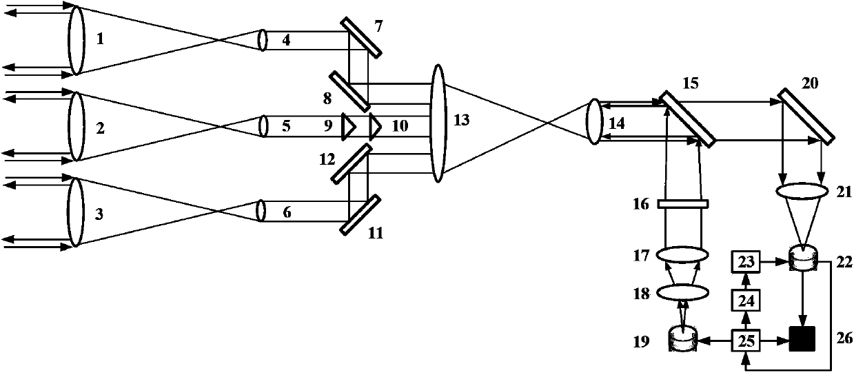
The invention relates to a three-dimensional imaging system for calculating correlation flight time by means of sparse aperture compression. The three-dimensional imaging system comprises a pulse light source emission unit, an expanded beam lens, a fourth collimating lens, a random optical modulation unit, a polarized light beam splitter, a first lens, a beam spot synthesis unit, a sparse aperture unit, a free space collimation unit, a beam reflection unit, a total-reflection mirror, a convergence light receiving lens, an optical detector, a flight time correlation unit and a compression calculation correlation algorithm module. The sparse aperture unit comprises at least three secondary telescope lenses, the free space collimation unit comprises at least three collimating lenses, and the beam reflection unit comprises at least three reflection mirror groups; one secondary telescope lens, one collimation lens and one reflection mirror form a light path; the flight time correlation unit comprises a pulse width regulation unit, an adjustable delay unit and a synchronous signal source.

Description

technical field [0001] The invention relates to the field of sparse aperture imaging, in particular to a three-dimensional imaging system and method for compressing and calculating associated time-of-flight with sparse apertures. Background technique [0002] Photon counting time-of-flight measurement technology and method is one of the key technologies of lidar and 3D imaging. The Lincoln National Laboratory of the United States took the lead in developing the single light counting 3D imaging technology based on time-of-flight, realizing the imaging of concealed mobile equipment in the battlefield environment. , mainly using photons to reflect multiple times through forest bushes to realize the measurement of hidden objects. At present, this technology has been applied in the civilian field. In China, the detection and protection of the landscape trees in Jingshan Park has achieved three-dimensional landscape imaging using the same technology. In addition, in archaeology a...

Claims


Application Information

Patent Timeline
IPC IPC(8): G01S17/89
Inventor 孙志斌俞文凯叶蔚然姚旭日翟光杰杨震孟新
Owner NAT SPACE SCI CENT CAS
Learn More