LED lighting device with light converging effect

a technology of led lighting and converging effect, which is applied in the direction of semiconductor devices for light sources, point-like light sources, lighting and heating apparatus, etc., can solve the problems of weak efficiency of the cylinders (b>54/b>) to reflect the light emitted from the leds (b>52/b>), and weaken the luminous intensity of the lighting device, so as to achieve the effect of enhancing the luminous intensity

Inactive Publication Date: 2006-11-30
HAOLI PRECISION IND
View PDF7 Cites 22 Cited by
  • Summary
  • Abstract
  • Description
  • Claims
  • Application Information

AI Technical Summary

Benefits of technology

[0009] The primary objective of the present invention is to provide an LED lighting device that can avoid light loss and converge light to enhance the luminous intensity in a certain direction. The LED lighting device has a circuit board with multiple LEDs, a light converging base and a cover. The light converging base is securely connected to the circuit board and has multiple reflecting cavities defined in the light converging base. Each reflecting cavity has a bore defined in a bottom of the reflecting cavity and corresponding to and receiving one of the LEDs. The depth of the reflecting cavities are larger than the length of the LEDs. The cover is combined with the light converging base to enclose the LEDs.

Problems solved by technology

But, in such a device, a significant portion of the light from the LEDs (44) is scattered sidewards, as shown in FIG. 5, upwards and downwards, as shown in FIG. 6, and thus weakens the luminous intensity in the frontward direction.
However, due to the cylindrical configuration of the hollow cylinders (54), the efficiency of the cylinders (54) to reflect the light emitted from the LEDs (52) is poor.
Third, after the frontward light passes through the integrated lenses (56) of the hollow cylinders (54), it has to pass through the cover (55), which weakens the luminous intensity of this lighting device due to transmission loss.
Additionally, the production cost of this lighting device is relatively expensive because of its complicated structure.

Method used


Image

  • LED lighting device with light converging effect
  • LED lighting device with light converging effect
  • LED lighting device with light converging effect

Examples


Embodiment Construction

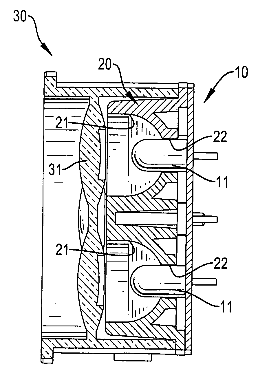
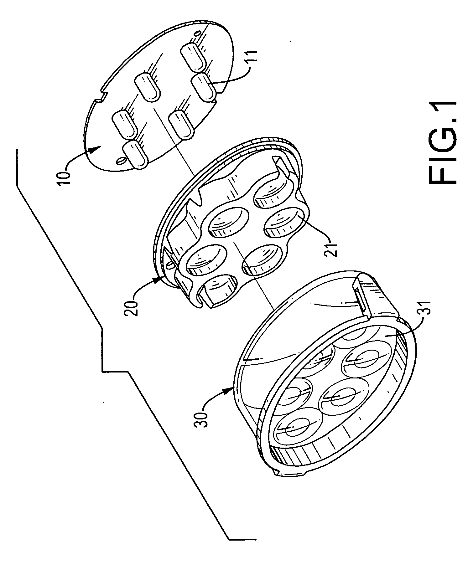
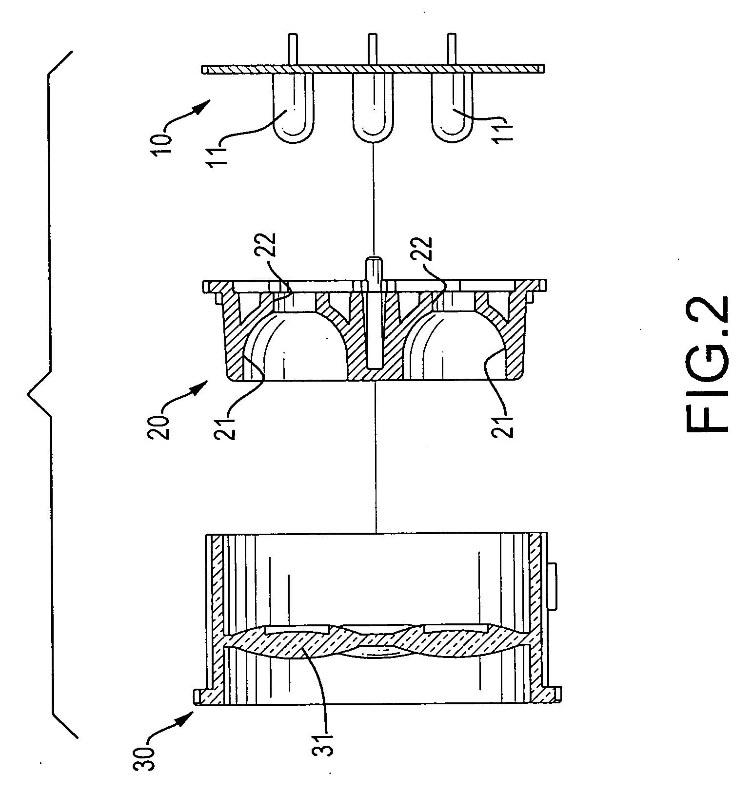
[0018] With reference to FIGS. 1 and 2, a lighting device in accordance with the present invention is installed in the casing and comprises a circuit board (10), a light converging base (20) and a cover (30).

[0019] The circuit board (10) has multiple LEDs (11) mounted thereon. The light converging base (20) has multiple reflecting cavities (21) defined on the light converging base (20) and each having an opening. In addition, multiple bores (22) are defined in bottoms of the reflecting cavities (21) to correspond to and receive the LEDs (11). Each cavity has a depth larger than a length of the corresponding LED. The cover (30) is cylindrical in shape and has multiple integrated lenses (31) formed therein to correspond to the reflecting cavities (21).

[0020] With further reference to FIG. 3, the LEDs (11) are respectively received in the corresponding bores (22) and extend into the reflecting cavities (21), and the integrated lenses (31) correspond respectively to the reflecting cav...


PUM


Abstract

An LED lighting device with light converging effect has a circuit board with multiple LEDs, a light converging base and a cover. The light converging base is securely connected to the circuit board and has multiple reflecting cavities defined in the light converging base. Each reflecting cavity has a bore defined in a bottom of the reflecting cavity and corresponding to and receiving one of the LEDs. Each cavity has a depth larger than a length of the corresponding LED. The cover is combined with the light converging base to enclose the LEDs.

Description

BACKGROUND OF THE INVENTION [0001] 1. Field of the Invention [0002] The present invention relates to a composition of a lighting device using multiple light emitting diodes (LEDs) as light sources, and more particularly to a LED lighting device having light converging effect to enhance the luminous intensity of the lighting device in a certain direction. [0003] 2. Description of Related Art [0004] Because of its high energy efficiency, long product life, and environmental friendly materials, the light emitting diode (LED) has become more and more popular as a light source in many applications. In one sort of applications thereof, the LED is used in illuminating lights, such as headlights of cycles and automobiles, and flashlights, in which the light emitted from the LED has to be converged to enhance the luminous intensity in the frontward direction so that objects in front of the users can be illuminated and seen clearly. [0005] With reference to FIGS. 4 to 6, a first conventional ...

Claims


Application Information

Patent Timeline
Patent Type & Authority Applications(United States)
IPC IPC(8): F21V13/04
CPCF21V5/007F21V5/04F21Y2101/02F21V13/04F21V7/0083F21Y2115/10
Inventor CHANG, HSIANG-CHUN
Owner HAOLI PRECISION IND
Why Eureka
Try Eureka