
Fiber optic connector having keyed ferrule holder

a fiber optic connector and ferrule holder technology, applied in the field of fiber optic connectors, can solve the problems of reducing signal transmission, unable to polish the two ferrule end faces in the same plane using conventional apparatus and processes, and the design of the hardened connector does not allow the separation of ferrules

Active Publication Date: 2006-11-30
CORNING OPTICAL COMM LLC
View PDF10 Cites 205 Cited by
  • Summary
  • Abstract
  • Description
  • Claims
  • Application Information

AI Technical Summary

Benefits of technology

[0008] One aspect of the invention is a duplex fiber optic connector including a first single fiber ferrule and a second single fiber ferrule arranged side-by-side, wherein the first and the second single fiber ferrules may be independently rotated between a first keyed position and a second keyed position. The first keyed position properly aligns the end face of the first ferrule and the end face of the second ferrule substantially in the same plane for simultaneous coplanar end face polishing us...

Problems solved by technology

In this regard, the removal of either too much or too little material during the process of polishing the end faces typically results in a misalignment of mating ferrules, which decreases signal transmission.
By aligning the ferrules side-by-side, with the ferrule end faces in different planes, it is not possible to simultaneously polish the two ferrule end faces in the same plane using conventional apparatus and processes.
When assembling a hardened duplex fiber optic connector using conventional LC or SC APC ferrules, the design of the hardened connector does not allow the ferrules to be separated and their end faces oriented into the same plane for simultaneous polishing.
By polishing the end faces individually, one end face may be polished differently than the other, thus resulting in connector-to-connector mating with improper end face contact and resulting signal loss.

Method used


Image

  • Fiber optic connector having keyed ferrule holder
  • Fiber optic connector having keyed ferrule holder
  • Fiber optic connector having keyed ferrule holder

Examples


Embodiment Construction

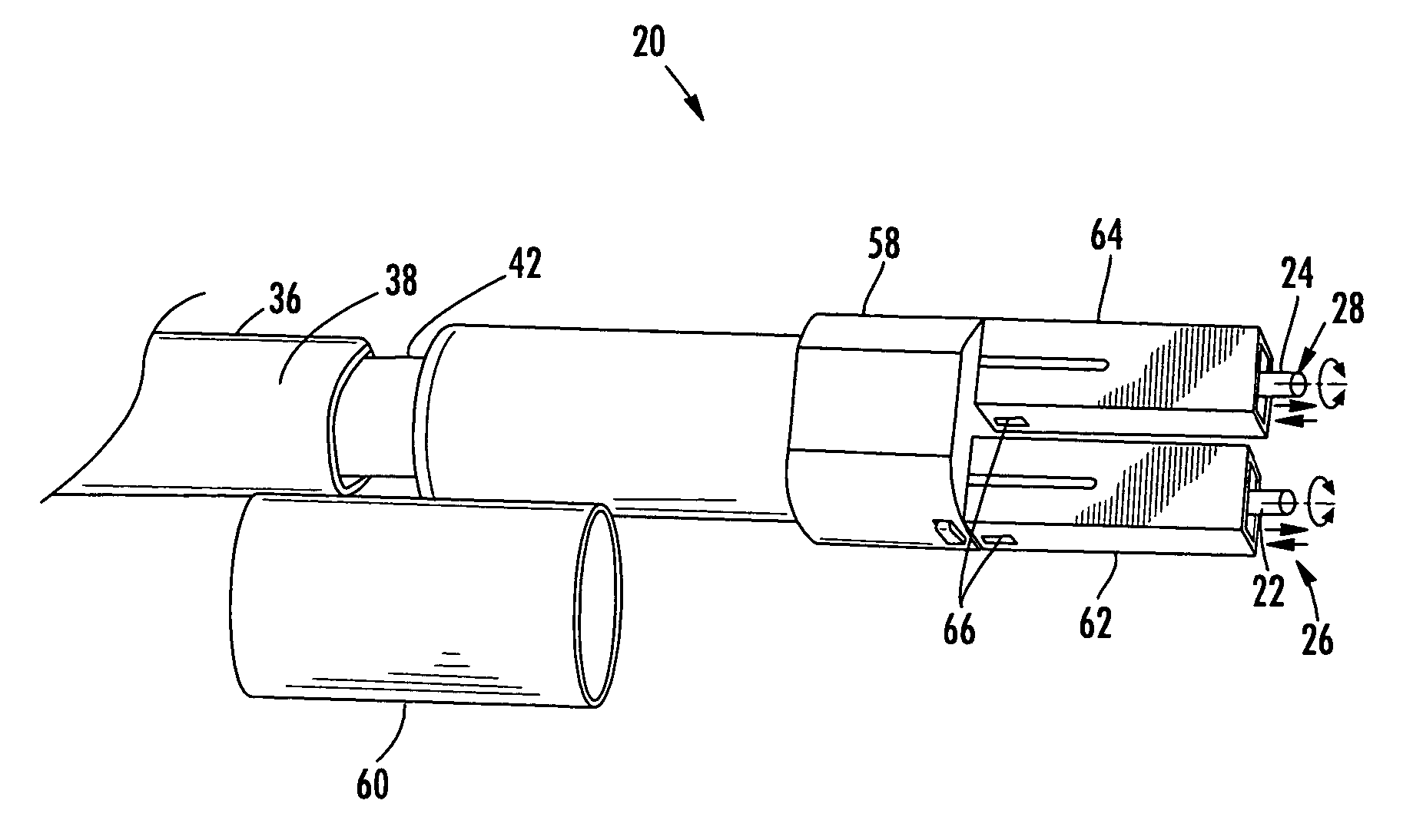
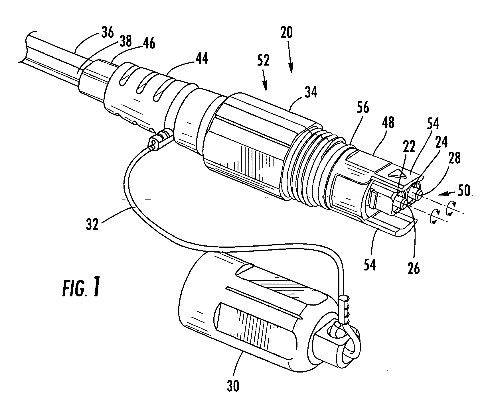
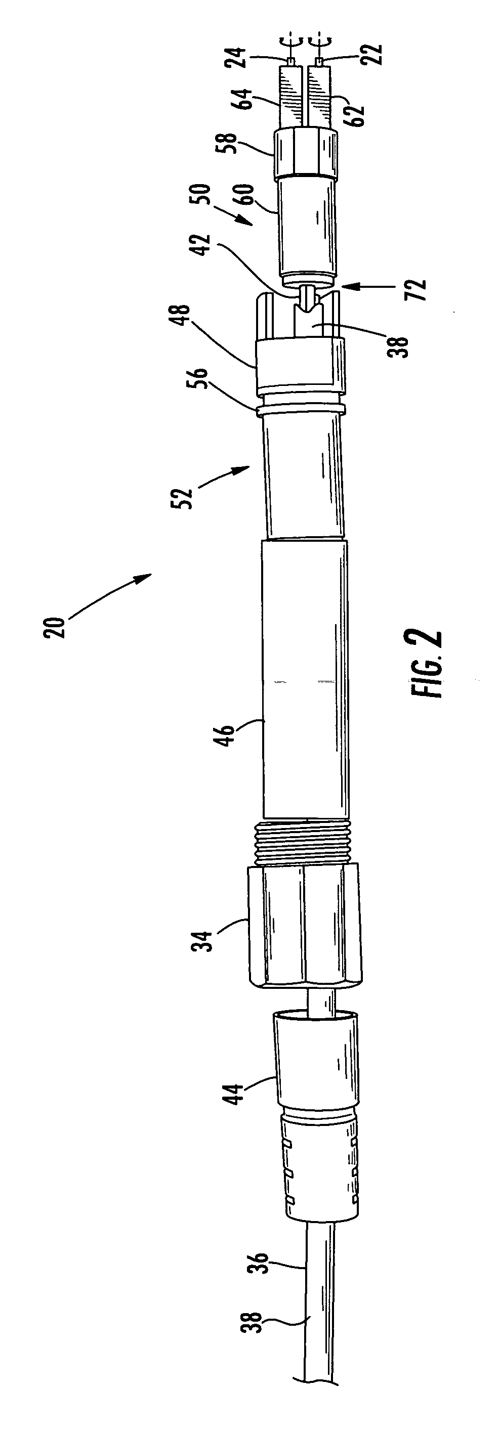
[0023] Reference will now be made in detail to the present preferred embodiments of the invention, examples of which are illustrated in the accompanying drawings. Whenever possible, the same reference numerals will be used throughout the drawings to refer to the same or like parts. An exemplary embodiment of a duplex fiber optic connector according to the invention is shown in FIG. 1 with the fiber optic connector designated generally throughout the various figures by reference numeral 20.

[0024] Referring now specifically to the accompanying drawings, FIGS. 1-6 show a duplex fiber optic connector 20 including two individual SC APC connectors mounted side-by-side on a duplex cable. As is known in the art, SC connectors include a single optical fiber in a standard-sized (2.5 mm diameter) ceramic ferrule. As is also known in the art, LC connectors hold a single optical fiber in a smaller (1.25 mm diameter) ceramic ferrule and may be used in environments in which a small form factor co...


PUM


Abstract

A fiber optic connector including one or more ferrule assemblies having a ferrule and a keyed ferrule holder defining a first key slot and a second key slot, and a connector housing defining a key that is received within the first or the second key slot. The first key slot configures the connector in a first keyed position for simultaneous, coplanar end face polishing of the ferrules, and the second keyed position configures the connector for mating with a receptacle, optical device or another connector. A fiber optic connector including a connector outer housing defining a first key slot for positioning the connector housing in a first keyed position and a second key slot for positioning the connector housing in a second keyed position, a connector inner housing defining a key and a ferrule assembly including a ferrule and a ferrule holder, wherein the ferrule assembly is biased outwardly within the connector outer housing. The connector outer housing is independently positionable between the first keyed position for end face polishing and the second keyed position for connector mating.

Description

BACKGROUND OF THE INVENTION [0001] 1. Field of the Invention [0002] The present invention relates generally to fiber optic connectors, and more specifically, to a duplex fiber optic connector having positionable ferrules that allow the ferrules to be rotated between a first keyed position for simultaneous coplanar end face polishing, and a second keyed position for mating with a receptacle, optical device or another connector of complimentary ferrule configuration with proper end face contact. [0003] 2. Technical Background [0004] A variety of optical connectors have been developed to facilitate the interconnection of optical fibers with other optical fibers, optical devices or the like. In this regard, a number of simplex, duplex and multi-fiber connectors including standard ferrules, such as SC, LC, FC, MU, MT and MTP, have been designed. A common type of connector includes an angled-physical-contact (APC) ferrule that is designed to make physical contact with another APC ferrule ...

Claims


Application Information

Patent Timeline
IPC IPC(8): G02B6/36
CPCG02B6/3822G02B6/3849G02B6/3878G02B6/3863G02B6/3871G02B6/3851
Inventor LUTHER, JAMES P.THEUERKORN, THOMASTRAN, HLEU V.
Owner CORNING OPTICAL COMM LLC
Learn More