
Optical image stabilizer for camera lens assembly

a technology camera lens, which is applied in the field of optical image stabilization, can solve the problems of inconvenient assembly, inconvenient correction, and high camera efficiency, and achieve the effect of clear imag

Inactive Publication Date: 2006-11-30
JAHWA ELECTRONICS +1
View PDF7 Cites 24 Cited by
  • Summary
  • Abstract
  • Description
  • Claims
  • Application Information

AI Technical Summary

Benefits of technology

[0015] Accordingly, the present invention has been made to solve the above-mentioned problems occurring in the prior art and provides additional advantages, by providing an optical image stabilizer of a camera lens assembly which can be embedded in a miniaturized photography device, such as a micro-digital camera and a mobile communication terminal, and can obtain a clear image even when the camera is shaken during operation.
[0016] One aspect of the present invention is to provide an optical image stabilizer of a camera lens assembly in which a camera device is moved according to a hand-shake of a user by using coils and permanent magnets so that the structure thereof is simplified, the control thereof is easy, and the manufacturing cost thereof is reduced.
[0017] Another aspect of the present invention is to provide an optical image stabilizer of a camera lens assembly which can improve the reliability of the product by employing a non-contact driving method.
[0018] Further aspect of the present invention is to provide an optical image stabilizer of a camera lens assembly in which ball bearings are inserted between a fixed body and a drive body so that the movement of the drive body can be smoothly performed during the hand-shake correcting operation.
[0019] Yet another aspect of the present invention is to provide an optical image stabilizer of a camera lens assembly in which a drive body is movable in at least two directions during the hand-shake correcting operation, thereby improving the correcting operation.

Problems solved by technology

However, since it corrects an image through a software, it requires dedicated memory or a high efficiency camera device and takes longer to correct.
Further, since there is a limit in removing an afterimage through a software, the correction rate is undesirably slow.
Since the OIS method needs a separate drive device, the manufacturing cost therefore increases and a separate installation space is needed.
Although the technology in which an optical lens is moved to correct an image in a digital camera having a space sufficient for embedding a drive section for driving the optical lens, it is difficult to employ such a technology in a miniaturized digital camera or a mobile communication terminal, which has many spatial restrictions.
However, since the outer diameter of the optical lens system increases to install the drive device such as the piezoelectric device at the outer periphery of the optical lens, it is difficult to mount the stabilizer to a mobile communication terminal having a restricted assembly length and diameter.
Further, since a considerable drive force must be generated to drive the optical lens of a predetermined weight, there is a limit in miniaturizing the drive device.
Lastly, since much electric power is needed, there is a limit in mounting the stabilizer to a portable photography device which uses charging batteries.
Hence, difficulties in designing a miniaturized drive device and the rise of manufacturing costs according to the increase in the number of parts are obstacles in securing the cost competitiveness of a photography device in which an image stabilizer is embedded.
Moreover, in the case of a contact-type drive device which uses frictional forces with a drive shaft such as a piezoelectric device, it is difficult to manage the tolerance of the contact surfaces.
In the event that the contact surface is worn, malfunction can be generated, thereby lowering the reliability.
Furthermore, since a drive circuit for generating and applying a predetermined voltage wave is required to drive the drive device such as the piezoelectric device, the manufacturing cost increases, and there is a restriction in simplifying the photography device.

Method used


Image

  • Optical image stabilizer for camera lens assembly
  • Optical image stabilizer for camera lens assembly
  • Optical image stabilizer for camera lens assembly

Examples


Embodiment Construction

[0029] Hereinafter, embodiments of the present invention will be described with reference to the accompanying drawings. For the purposes of clarity and simplicity, a detailed description of known functions and configurations incorporated herein is omitted to avoid making the subject matter of the present invention unclear.

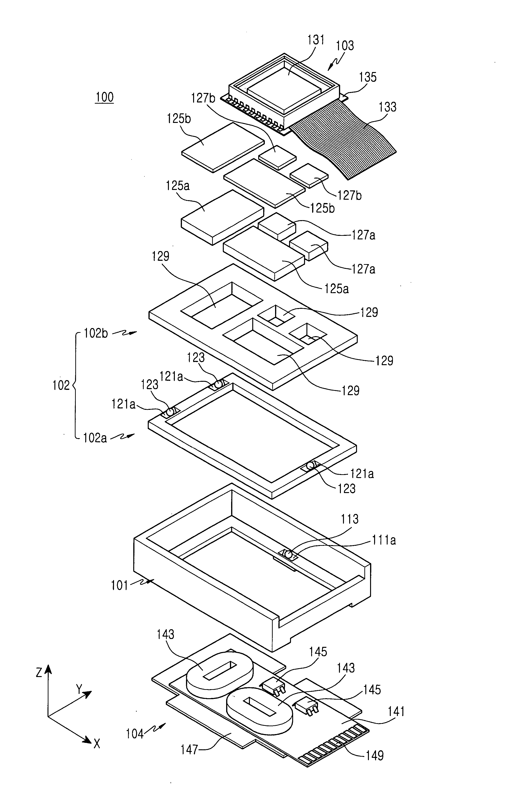
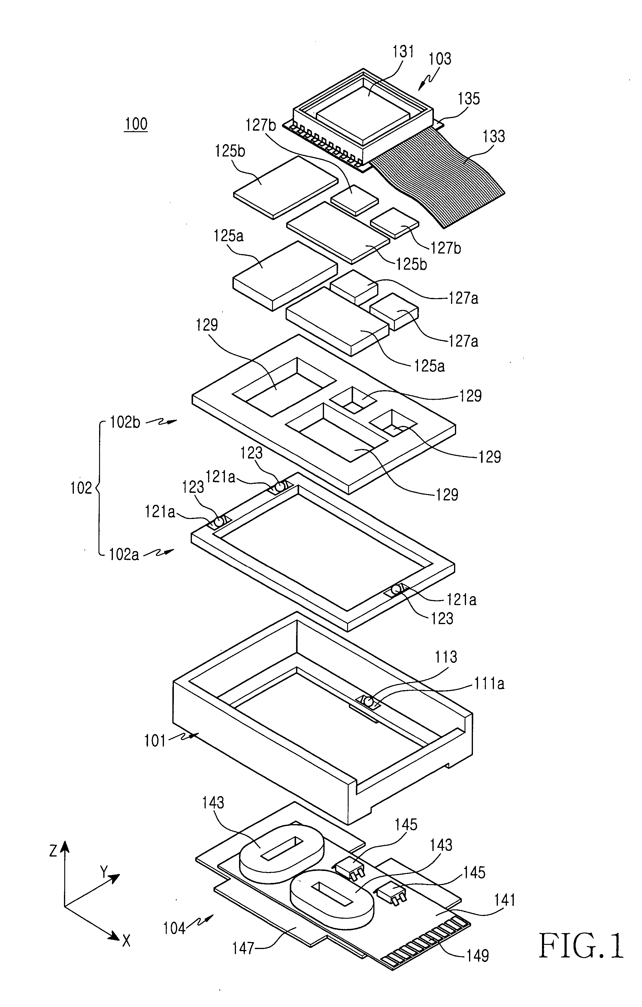
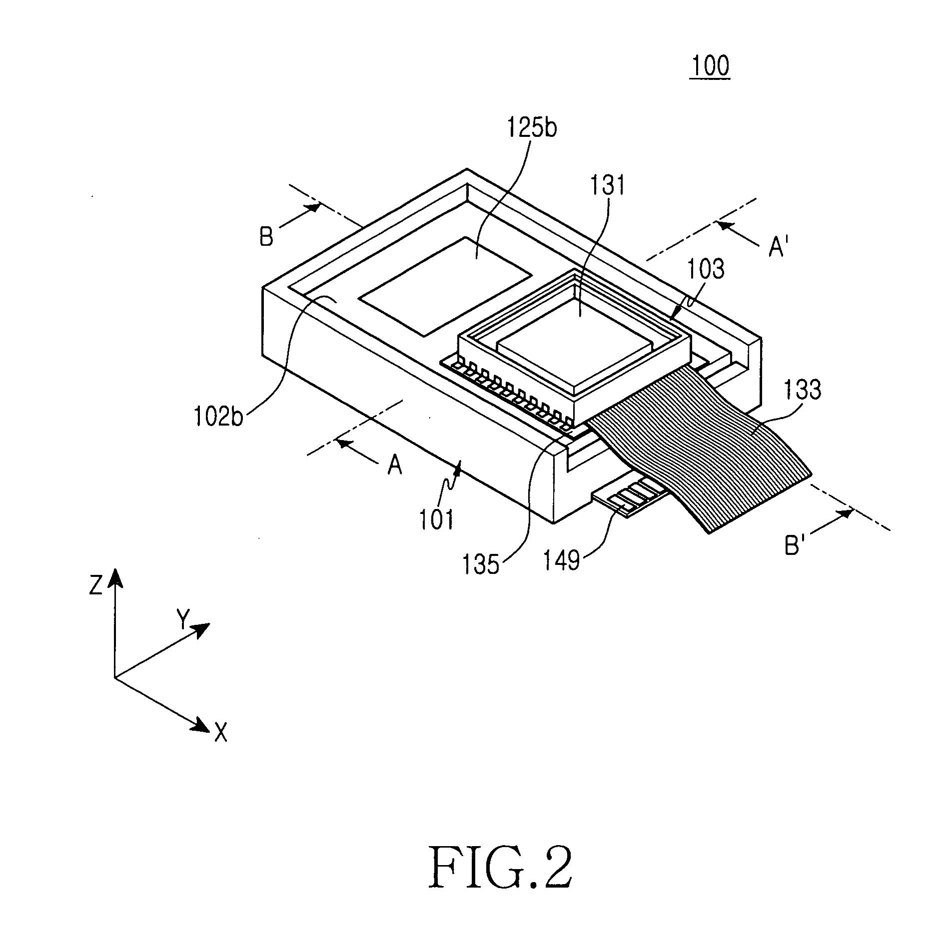
[0030] As shown in FIGS. 1, 2, 5, and 6, an optical image stabilizer 100 of a camera lens assembly according to the first preferred embodiment of the present invention includes a main frame 101, a drive frame 102, coils 143, and permanent magnets 125a. The optical image stabilizer 100 corrects image blurring arising from a hand-shake, by moving the drive frame 102 on the main frame 101 using interactions between the coils 143 and the permanent magnets 125a, thereby changing the position of a camera device 103.

[0031] A portion of the upper surface of the main frame 101 is opened so that a subject image can be introduced into a camera device 103. First slide recess...


PUM


Abstract

Disclosed is an optical image stabilizer for a camera lens assembly, which includes: a main frame; a drive frame moving on the main frame in at least one direction; a camera device mounted to the drive frame; a pair of driving permanent magnets installed at one of the main frame and the drive frame; and a pair of coils installed at the other of the main frame and the drive frame and opposite to the driving permanent magnets, wherein the drive frame is moved by interactions of the electromagnetic forces generated when currents are applied to the coils.

Description

CLAIM OF PRIORITY [0001] This application claims priority to an application entitled “OPTICAL IMAGE STABILIZER FOR CAMERA LENS ASSEMBLY,” filed with the Korean Intellectual Property Office on May 26, 2005 and assigned Serial No. 2005-44544, the contents of which are incorporated herein by reference. BACKGROUND OF THE INVENTION [0002] 1. Field of the Invention [0003] The present invention relates to a camera lens assembly, and more particularly to an optical image stabilizer mounted to a digital camera or a mobile communication terminal for correcting an image blurred by a hand-shake of a user. [0004] 2. Description of the Related Art [0005] A mobile communication terminal equipped with a camera function is being commonly used today. [0006] Just as in a regular camera, images can be blurred using mobile communication terminals. [0007] Although high resolution cameras are available with the progress of the optical technology, optical image stabilizers are needed to reduce the effect o...

Claims


Application Information

Patent Timeline
Patent Type & Authority Applications(United States)
IPC IPC(8): G03B17/00
CPCG02B27/646G03B5/02H04N5/23287H04N5/23248H04N5/23258H04N5/2253H04N23/54H04N23/68H04N23/6812H04N23/687G03B5/00G03B2205/0069H04N23/55
Inventor SHIN, JEONG-KILSHIN, DOO-SIKLEE, JONG-PILKIM, HEE-SEUNGSEOL, JIN-SOO
Owner JAHWA ELECTRONICS
Features
  • Generate Ideas
  • Intellectual Property
  • Life Sciences
  • Materials
  • Tech Scout
  • Unparalleled Data Quality
  • Higher Quality Content
  • 60% Fewer Hallucinations
Learn More