
Biological fluid treatment and disposal apparatus and method

a technology for biological fluids and disposal apparatuses, applied in the field of biological fluid treatment and disposal apparatuses, can solve the problems of complex apparatuses involved, complex construction, and equally complex operation, and achieve the effect of enabling the proper disinfection and disposal

Inactive Publication Date: 2006-11-30
WHITE JAMES M
View PDF3 Cites 3 Cited by
  • Summary
  • Abstract
  • Description
  • Claims
  • Application Information

AI Technical Summary

Benefits of technology

[0014] It is among the objects of the present invention to provide a treatment and disposal system that effectively and efficiently enables the proper disinfection and disposal of biological fluids and other fluid wastes.
[0015] It is further among the objects of the present invention to reduce the costs of fluid treatment and disposal apparatus and the costs of operation of such apparatus.
[0018] It is yet another of the objects of the invention to provide an apparatus for the treatment of fluids in a continuous, rather than a batch, process to enable the treatment and disposal of any quantity of fluid without requiring intermittent operation of the apparatus.

Problems solved by technology

Although the apparatus and systems known in the prior art may be effective in treating biological waste materials, they suffer from certain disadvantages and drawbacks.
The apparatus involved is complex and costly in construction, and may be equally complex to operate.
Such apparatus, because of its relative mechanical and electrical / electronic complexity, also requires regular maintenance and repair, which may make the apparatus unavailable for use when needed.

Method used


Image

  • Biological fluid treatment and disposal apparatus and method
  • Biological fluid treatment and disposal apparatus and method
  • Biological fluid treatment and disposal apparatus and method

Examples


Embodiment Construction

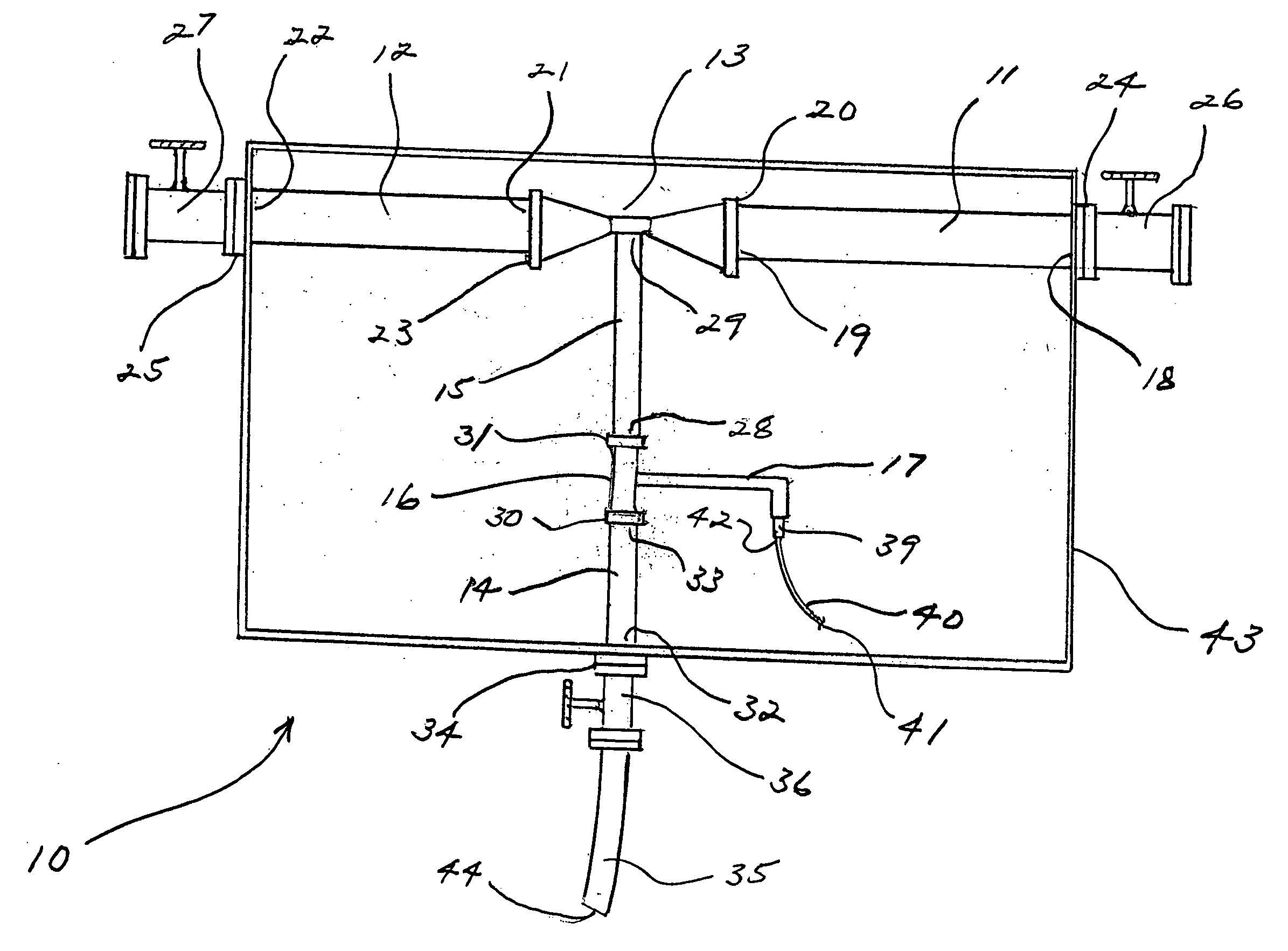
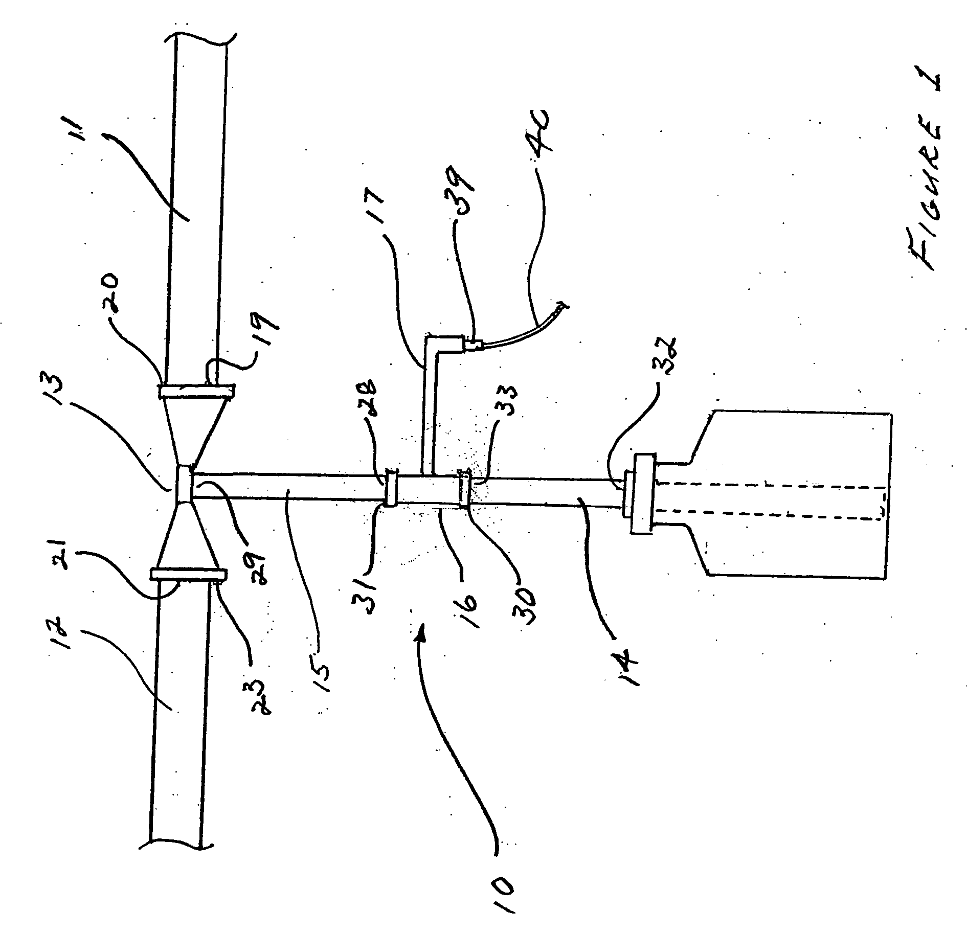
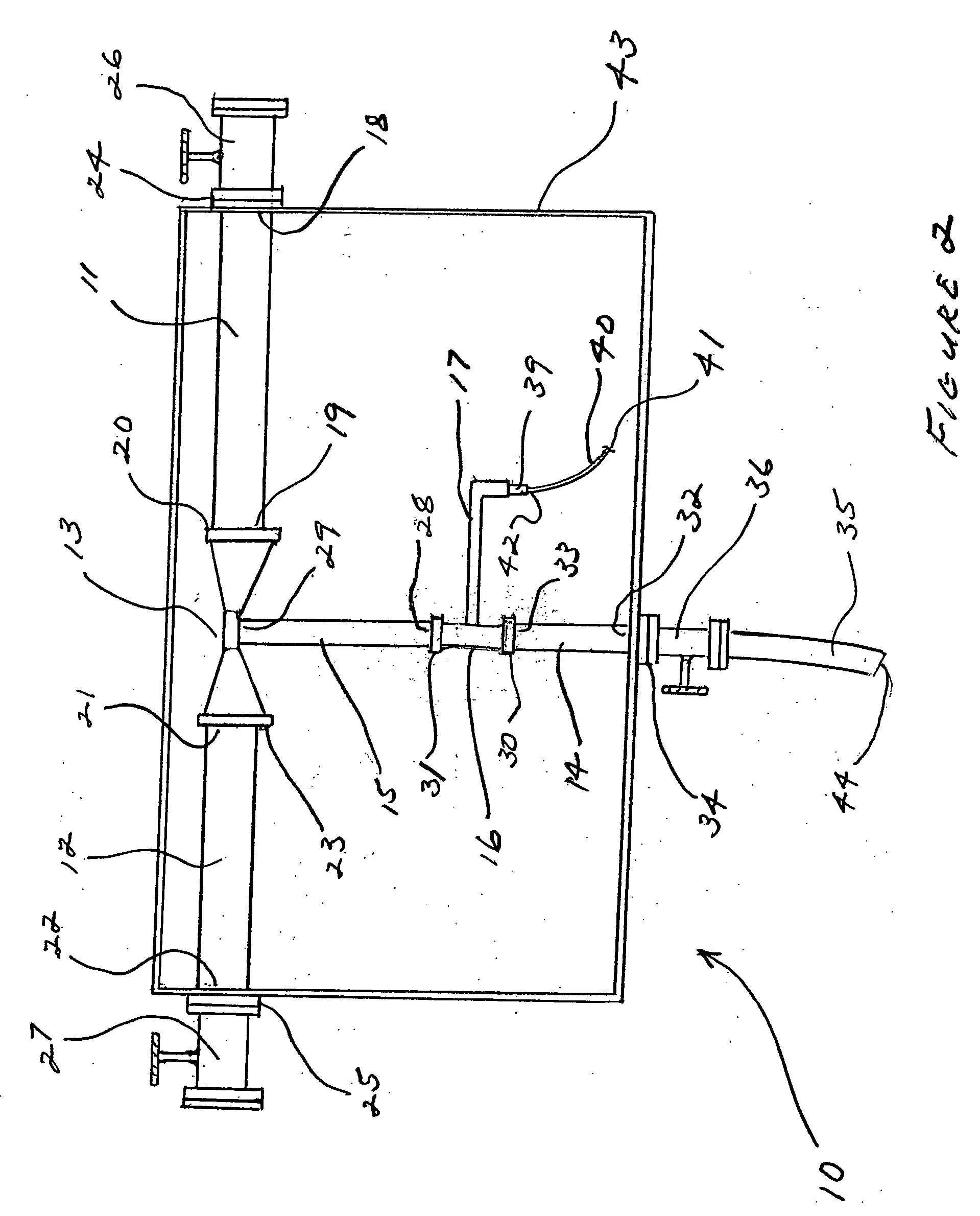
[0028] The preferred embodiment of the apparatus of the invention, generally designed by reference number 10, includes as its principal components a motive and carrier fluid inlet line 11, a disposal line 12, a primary venturi 13, connected in coaxial alignment between the motive fluid inlet line and the disposal line, a waste fluid inlet line 14, a treated waste line 15, mixing chamber 16 coaxially connected between the waste inlet line and the treated waste line, and a disinfectant line 17. Although the composition of the motive and carrier fluid used in the operation of the apparatus of the invention, flowing through line 11, is not limited to any particular fluid, it is contemplated that in the majority of instances water will be used as the motive and carrier fluid, and line 11 may also be referred to as a water inlet line. Similarly, references to water as the motive and carrier fluid are not intended as limitations, and it is to be understood that other fluids could be used w...


PUM

PropertyMeasurementUnit
Pressureaaaaaaaaaa
Flow rateaaaaaaaaaa
Volumetric flow rateaaaaaaaaaa

Abstract

An apparatus for treating and disposing of liquid waste, including but not limited to biological fluids, from a waste container includes a motive and carrier liquid flow passageway including a first venturi, a liquid waste flow passageway including a mixing chamber, connected to the first venturi so as to impose a suction and draw waste from a waste container through the liquid waste flow passageway when motive and carrier liquid is flowing through the first venturi; and a disinfectant line connected between a source of liquid disinfectant and the mixing chamber, so as to impose a suction and automatically draw liquid disinfectant through the disinfectant line to mix with the liquid waste when liquid waste is flowing through the mixing chamber. An alternative embodiment includes a backwash passageway with a backwash venturi to which the disinfectant line is connected, for selectively washing a waste container with a disinfectant solution.

Description

RELATED APPLICATION DATA [0001] This application is a Continuation-In-Part of U.S. patent application Ser. No. 09 / 526,370, filed Jun. 19, 2000, and titled “Biological Fluid Disposal System”; and this application also claims the benefit of U.S. Provisional Patent Application Ser. No 60 / 762,843.FIELD OF THE INVENTION [0002] The present invention generally relates to systems and apparatus for the disposal of contaminated fluids, and in its preferred embodiments more particularly relates to apparatus for conveying biological fluids from collection or storage containers to disposal, with disinfectant treatment of the fluids while the fluids are conveyed to disposal. BACKGROUND AND PRIOR ART [0003] For a number of years, hospitals and other healthcare facilities have sought a safe and efficient means for handling and disposing of potentially hazardous biological fluids collected from patients during surgery and other procedures. It is very important to limit, if not fully eliminate, the e...

Claims


Application Information

Patent Timeline
IPC IPC(8): C02F1/50
CPCA61L11/00C02F2103/003C02F1/686C02F1/50
Inventor WHITE, JAMES M.
Owner WHITE JAMES M
Learn More