
Pipeless water jet assembly

a water jet and assembly technology, applied in the field of jet assembly, can solve the problems of difficult and sometimes almost impossible to thoroughly clean and/or disinfect, all the water jet producing devices in existence today, and high cost and time consumption, and achieve the effects of reducing bacterial problems, high volume and high velocity water flow

Active Publication Date: 2021-06-01
BROOKS STEVENS
View PDF7 Cites 0 Cited by
  • Summary
  • Abstract
  • Description
  • Claims
  • Application Information

AI Technical Summary

Benefits of technology

This patent describes a water jet apparatus that uses a toroidal soliton effect to pump water without the need for disassembly to maintain cleaning. It also provides a means to create a massaging feel, destroy bacteria, and does not require circulation pipes or pumps between the inlet and outlet of the discrete jet assemblies. Additionally, it can be properly disinfected after use without physical scrubbing or cleaning and does not have a single continuous elongated flow of water directed into and then out of the spa apparatus. These features make the water jet apparatus unlike any other device in use today.

Problems solved by technology

However, all of the water jet producing devices in existence today have disadvantages including being difficult and sometimes almost impossible to thoroughly clean and / or disinfect.
While it is accepted that diligent adherence to published procedures for cleaning and / or treatment can often maintain a desired level of clarity and sanitary condition of the water associated with such appliances, many such processes are commonly complicated, costly and time consuming such that such cleaning procedures are rarely strictly adhered to and / or followed.
More aggressive cleaning protocols can require the user or service personnel to disassemble pump and jet assemblies such that disassembly of pump impellers, screens and / or stators, etc, such that the cleaning process takes an inordinate amount of time and associated with the inability to use the respective appliance.
Such service and cleaning down time considerations cost commercial users of such devices to lose income as well as endure the expense associated with such services and the intermediate chemical treatments.
In the case of consumers, complicated cleaning procedures of piped or even pipe free water jet systems are hardly, if ever, strictly adhered to.
Such inattention can result in the collection of the undesired matter in the jet system which is expelled into the user environment upon subsequent operation of the jet system.
Despite such efforts, however, water quality is sometimes still difficult to maintain.
The destruction of the outer coating or barrier is generally successful with chemicals alone but most often times chemicals are only effective in destroying the outer barrier when used for extended periods of time, sometimes hours.
Unfortunately, many spa devices have intricate and elaborate systems of passages, cavities, orifices and pipes that move water from a pump, through a filtering system, and ultimately to one or more nozzles (e.g., openings) that deliver water back to a basin for re-circulation.
The various pipes and fittings often render it difficult if not impossible to mechanically scrub every component that comes into contact with the circulated water.
Further, after a system is drained, some water commonly remains within the piping system, usually in cracks, crevices, and low portions of the circulation loop.
For example, the pump itself is usually a sealed unit that may be difficult to completely drain.
Consequently, water quality may be diminished in conventional piped systems that are not effectively cleaned.
The jet streams produced are harsh and can become uncomfortable after only a few minutes of use.
Such actions commonly satisfy the desires of one user to the detriment of the desires of other users.
Many customers often complain that the jets of water produced in this manner are too rough, in some cases even producing pain or discomfort.
This type of system can have several disadvantages including producing unrestricted streams of water.

Method used


Image

  • Pipeless water jet assembly
  • Pipeless water jet assembly
  • Pipeless water jet assembly

Examples


Embodiment Construction

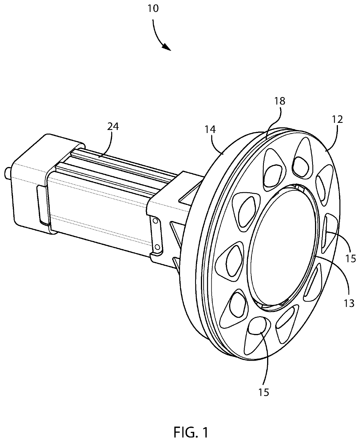
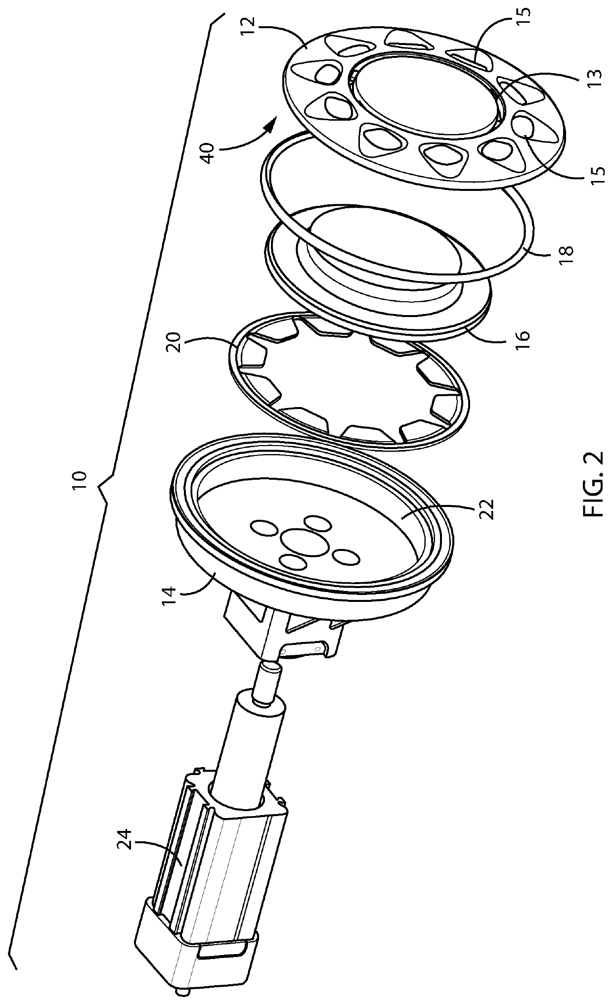
[0069]It is appreciated that, while the disclosed embodiments are illustrated as a jet apparatus designed for bathtubs, spas, whirlpools, hot tubs and the like, the present invention discloses and includes features that have a much wider applicability. For instance, it is appreciated that the present invention is usable with various tub, pool, and / or spa designs which can be adapted for various uses such as hand spas, other body parts, entire bodies, one or multiple persons, etc. Further, the size and relative orientation of the various components and the size of the apparatus can be widely varied. It is further appreciated that the various jet assemblies disclosed herein can be usable in other applications such as fluid mixing or agitation systems.

[0070]It is further appreciated that the particular materials used to construct the exemplary embodiments are also illustrative. Components of the device, assembly, or apparatus can be manufactured from thermoplastic resins such as inject...


PUM


Abstract

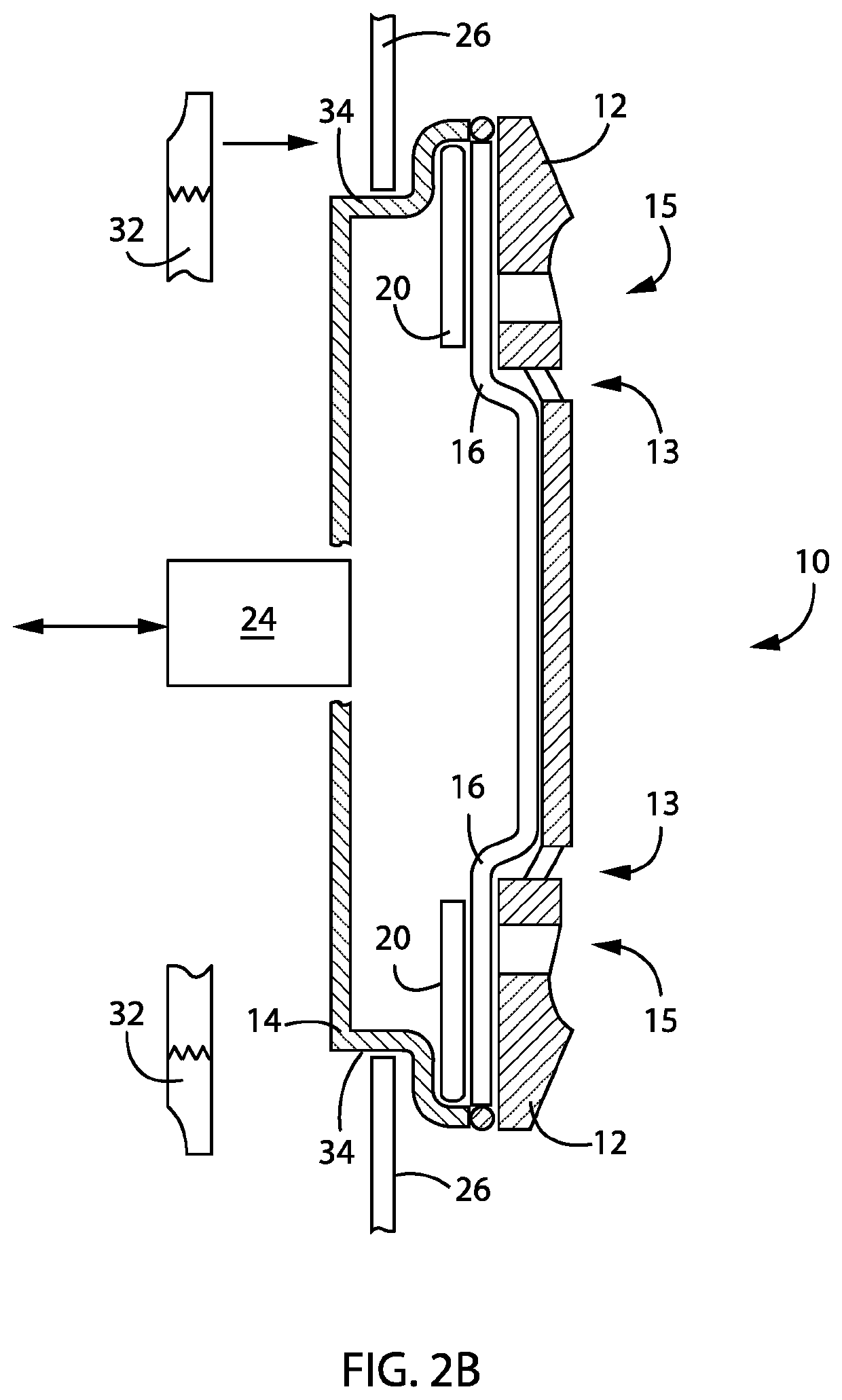
A water jet assembly includes a faceplate with at least one opening, a housing constructed to cooperate with the faceplate, and a mover disposed within a chamber of the housing. The mover is configured to move between a first position adjacent the at least one opening of the face plate and a second position offset from the faceplate to provide a variable volume within the chamber. The water jet assembly also includes an exciter connected to the housing and configured to transition the mover between the first position and the second position to increase and decrease the volume to move fluid into and out of the chamber via the at least one opening.

Description

CROSS REFERENCE TO RELATED APPLICATIONS[0001]This application is a continuation-in-part and claims priority to U.S. Utility patent application Ser. No. 15 / 988,469 filed on May 24, 2018 titled “Pipeless Water Jet Assembly”, which is a continuation of U.S. Utility patent application Ser. No. 14 / 733,049 filed on Jun. 8, 2015 titled “Pipeless Water Jet Assembly”, which claims priority to U.S. Provisional Patent Application No. 62 / 008,661 filed on Jun. 6, 2014 titled “Pipeless Water Jet Assembly” and the disclosures of which are incorporated herein.FIELD OF THE INVENTION[0002]The present invention relates to a jet assembly for generating a massaging pulse of water commonly associated with whirlpools, hot tubs, pedicure spas, swimming pools, bathtubs, medical tubs, and other such devices that are commonly subsequently cleaned and / or disinfected prior to subsequent use.BACKGROUND OF THE INVENTION[0003]It is generally known to provide a jet stream of water in such products as health and swi...

Claims


Application Information

Patent Timeline
Patent Type & Authority Patents(United States)
IPC IPC(8): A61H33/00
CPCA61H33/6057A61H33/0087A61H33/6063A61H1/00A61H2201/1215A61H2201/1238A61H2201/1418A61H2201/5056A61H2203/02
Inventor KONSTANTAKIS, GEORGE C.BERRITTA, ROBERTODAMM, RYAN M.LIPPINCOTT, STEVEN M.HUBBARD, BRIAN W
Owner BROOKS STEVENS
Learn More