Connector fitting structure

a technology of connecting parts and fittings, applied in the direction of coupling device connection, engagement/disengagement of coupling parts, electrical apparatus, etc., can solve the problems of difficult pivotal movement of levers, not smoothly moving within, and not smoothly in a stable manner, so as to reduce the cost, operate smoothly, and reduce the force required for operating levers

Active Publication Date: 2006-11-30
YAZAKI CORP
View PDF6 Cites 13 Cited by
  • Summary
  • Abstract
  • Description
  • Claims
  • Application Information

AI Technical Summary

Benefits of technology

[0037] In the above fitting structure, the lever of the single-side construction is supported on the one side surface of the connector housing, and therefore the connector housing can be formed into a compact design, and besides the construction of the lever is simple, and therefore the cost can be reduced.
[0038] In the connector fitting structure of the present invention, the lever is pivotally moved in stages, and therefore the lever can be operated smoothly in a stable manner, and besides the radius of pivotal movement of the lever, as well as the force required for operating the lever, can be reduced, and the connector fitting operation can be carried out easily and positively with the low insertion force by the smooth pivotal movement of the lever. Furthermore, the lever of the single-side construction is used, and therefore the compact design of the connector housing can be achieved, and also the cost can be reduced.

Problems solved by technology

However, in the above conventional lever-type connector 100 shown in FIGS. 17 and 18, when the lever 101 was pivotally moved so as to fit the two housings 103 and 105 together, the projecting portion 104 could not smoothly move within the engagement hole 102, thus inviting a problem that it was difficult to pivotally move the lever 101 smoothly in a stable manner.
Another problem is that the radius of pivotal movement of the lever 101, as well as the force required for operating the lever, was increased.

Method used


Image

  • Connector fitting structure
  • Connector fitting structure
  • Connector fitting structure

Examples


Embodiment Construction

[0057] A preferred embodiment of the present invention will now be described with reference to the drawings.

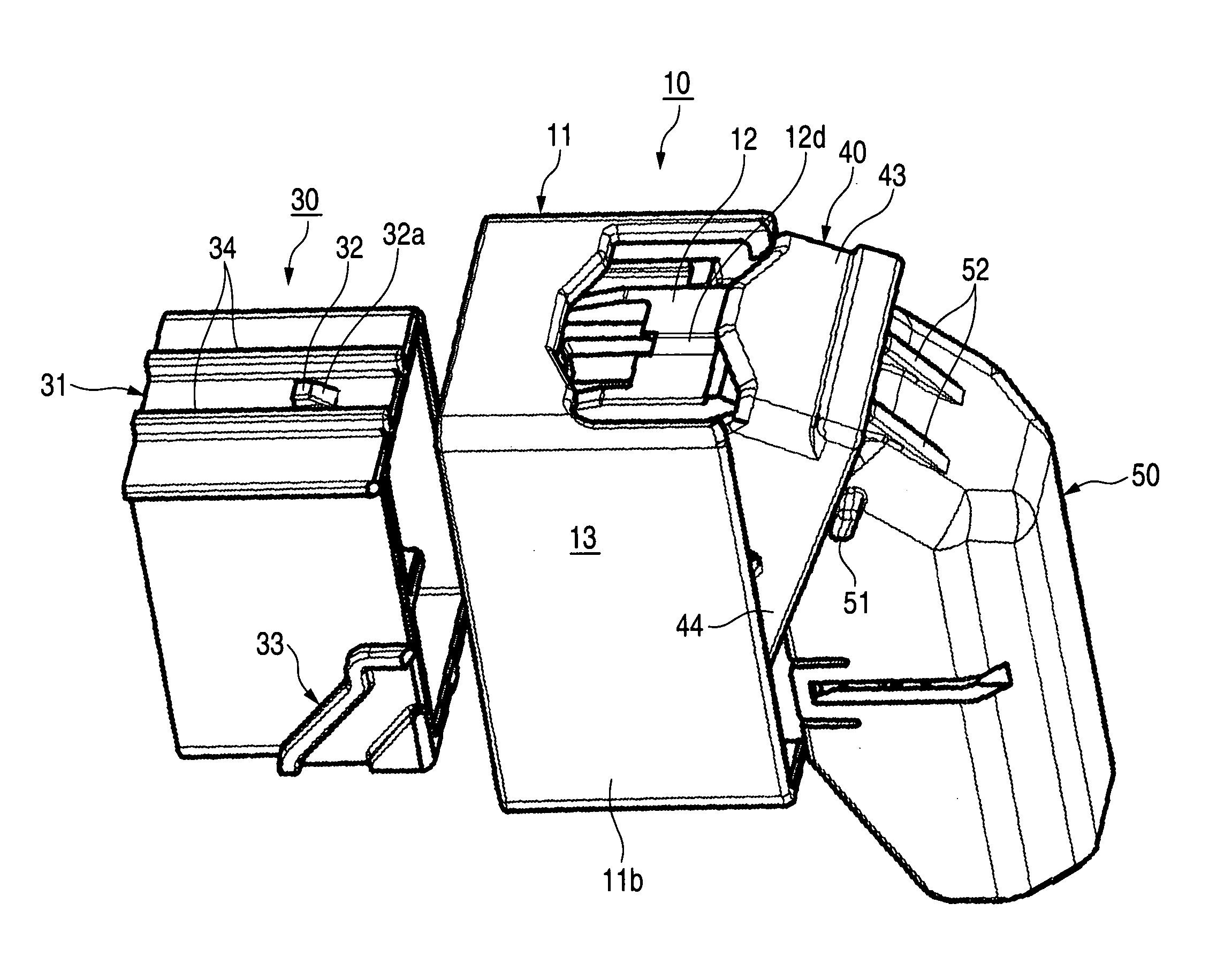
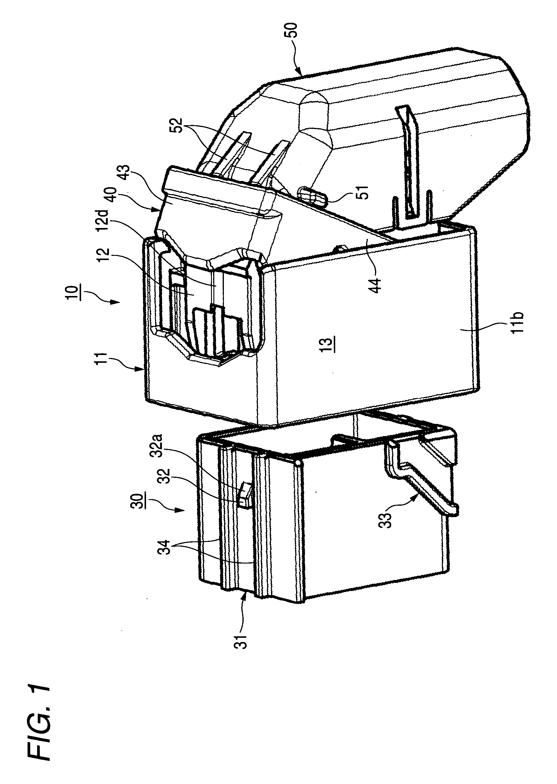
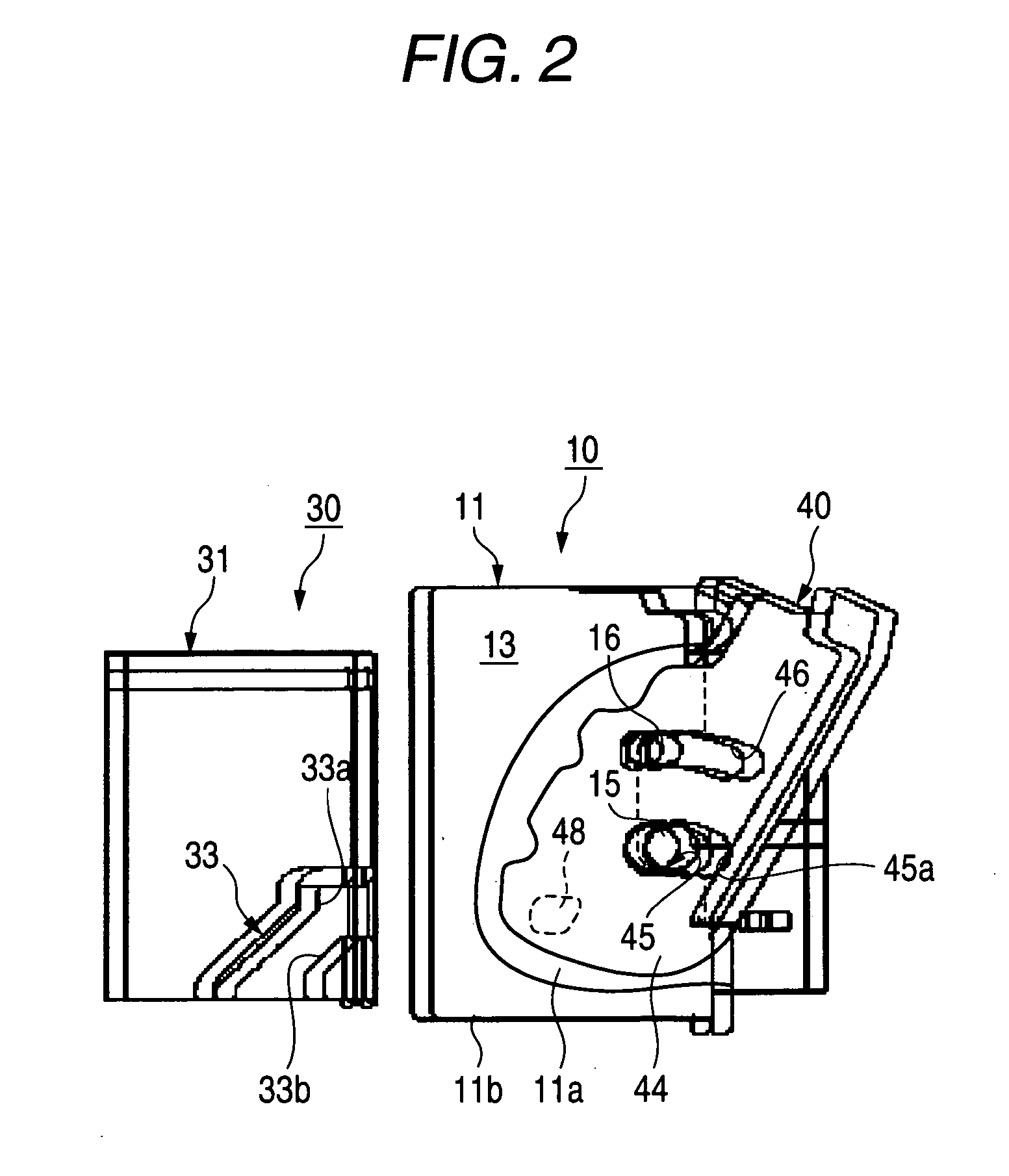
[0058]FIG. 1 is a perspective view of one preferred embodiment of a connector fitting structure of the invention, showing a condition before a male connector is fitted in a female connector, FIG. 2 is a side-elevational view of the connector fitting structure of FIG. 1, with a cover removed and also with an outer housing of the female connector partly broken, FIG. 3 is a cross-sectional view of the connector fitting structure of FIG. 1, showing a cut surface where a lock arm of the female connector can be seen, and FIG. 4 is a cross-sectional view of the connector fitting structure of FIG. 1, showing a cut surface where a lock cancellation arm of a lever can be seen.

[0059]FIG. 5 is a perspective view of the connecting fitting structure of this embodiment, showing an initial stage of the fitting of the male connector into the female connector. FIGS. 6 and 7 are side-elevation...


PUM


Abstract

At a first stage of a pivotal movement of a lever, a housing-side boss slides in a fitting groove in the lever, and a fitting/disengagement projection is brought into abutting engagement with an engagement surface provided in a fitting/disengagement guide portion, and the boss is displaced to an abutment portion provided in the fitting groove. At a second stage of the pivotal movement, the lever is pivotally moved about the housing-side boss, and the fitting/disengagement projection is slid in and guided by the fitting/disengagement guide portion, so that a male connector can be completely fitted into a female connector.

Description

BACKGROUND OF THE INVENTION [0001] 1. Field of the Invention [0002] This invention relates to a connector fitting structure in which a pair of female and male connectors are fitted together in a locked condition, and more particularly to the structure of a lever-type connector for effecting a fitting operation by pivotally moving a lever. [0003] 2. Related Art [0004] Various conventional lever-type connectors are already known (see, for example, JP-A-2002-359028 Publication (Pages 5 to 6, FIGS. 2 and 3)). FIG. 17 is a cross-sectional view of a lever-type connector disclosed in Patent Literature 1, showing a condition before a male housing is fitted in a female housing, and FIG. 18 is a cross-sectional view of the lever-type connector of FIG. 17, showing a condition in which the male housing is fitted in the female housing. [0005] Referring to FIGS. 17 and 18, in the lever-type connector 100, a projecting portion 104 of the male housing 103 is engaged in an engagement hole 102 formed...

Claims


Application Information

Patent Timeline
Patent Type & Authority Applications(United States)
IPC IPC(8): H01R13/62
CPCH01R13/62938H01R13/62955H01R13/6295
Inventor OHTAKA, KAZUTOOHSUMI, HIDEKI
Owner YAZAKI CORP
Why Eureka
Try Eureka