Systems and methods of self test for a slowly varying sensor

a self-testing and sensor technology, applied in wave based measurement systems, instruments, calibration apparatus, etc., can solve the problem of substantially higher oversampling rate of normal operation filters than that of self-test filters

Active Publication Date: 2006-12-07
TEXAS INSTR INC
View PDF4 Cites 7 Cited by
  • Summary
  • Abstract
  • Description
  • Claims
  • Application Information

AI Technical Summary

Problems solved by technology

Indeed, in some cases, the oversampling rate of the normal operation filter is substantially higher than that of the self test filter.

Method used


Image

  • Systems and methods of self test for a slowly varying sensor
  • Systems and methods of self test for a slowly varying sensor
  • Systems and methods of self test for a slowly varying sensor

Examples


Embodiment Construction

[0021] The present invention is related to systems and methods for monitoring the operation of a sensor, and in particular to systems and methods for testing the operation of a slowly varying sensor.

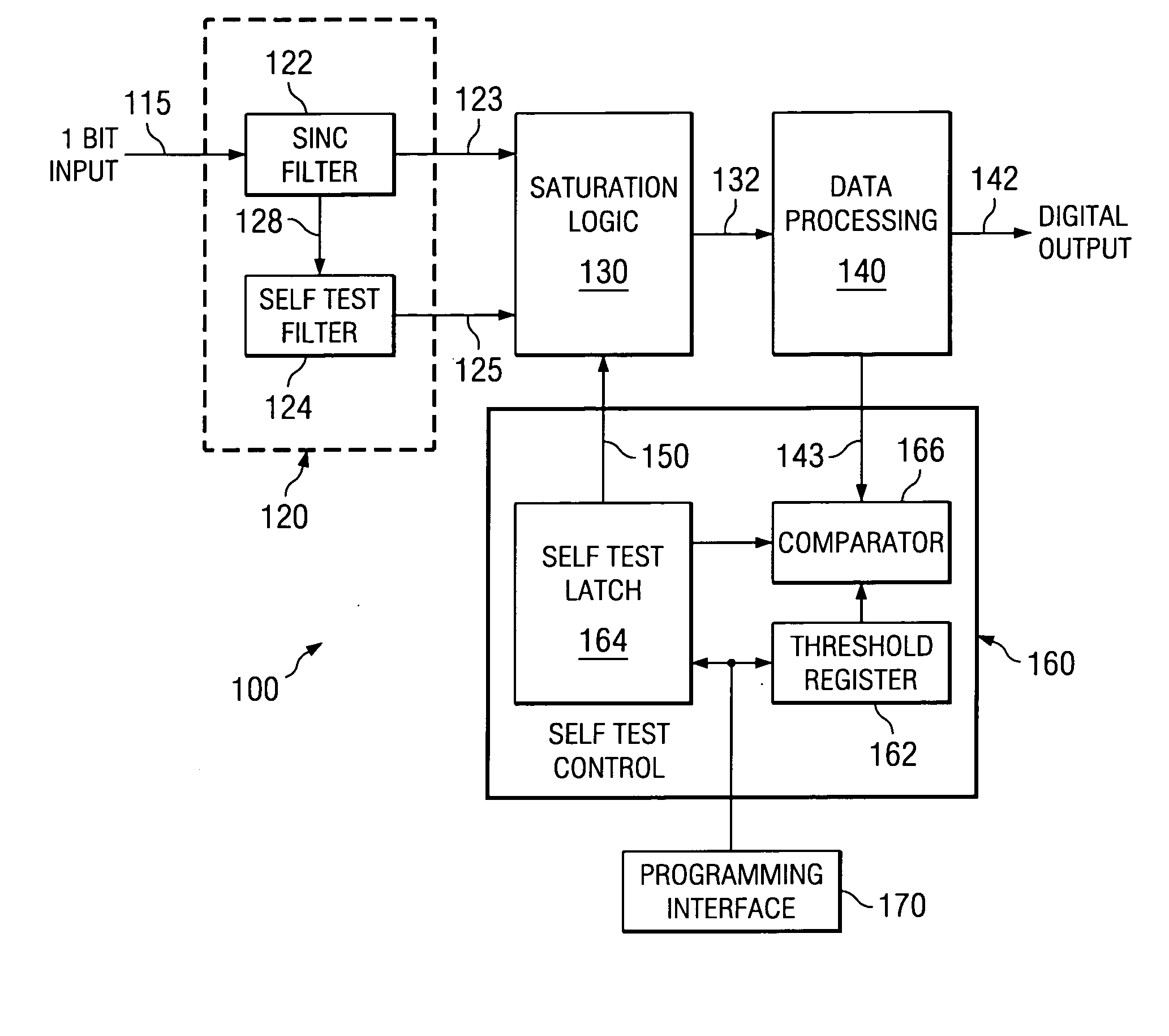
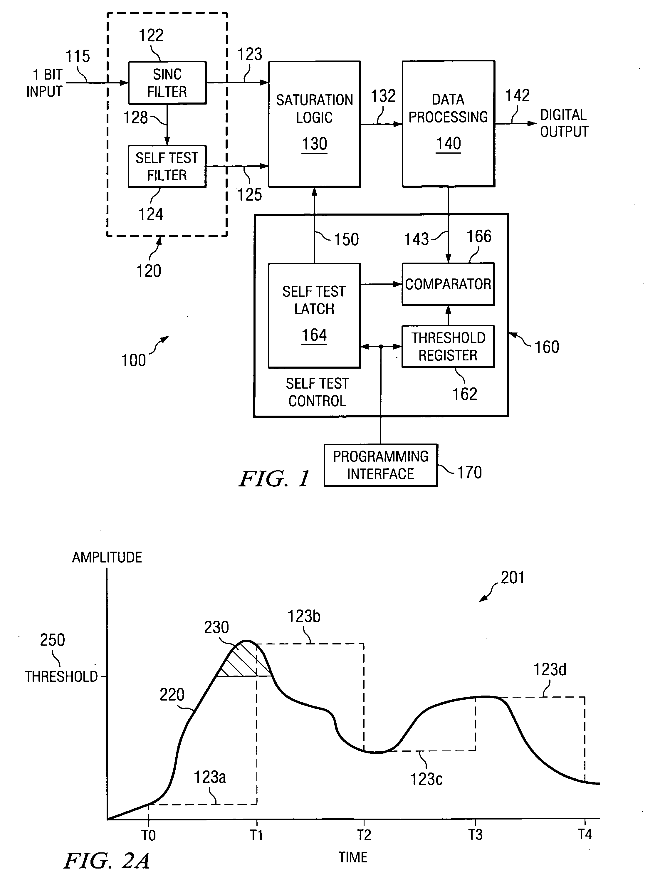
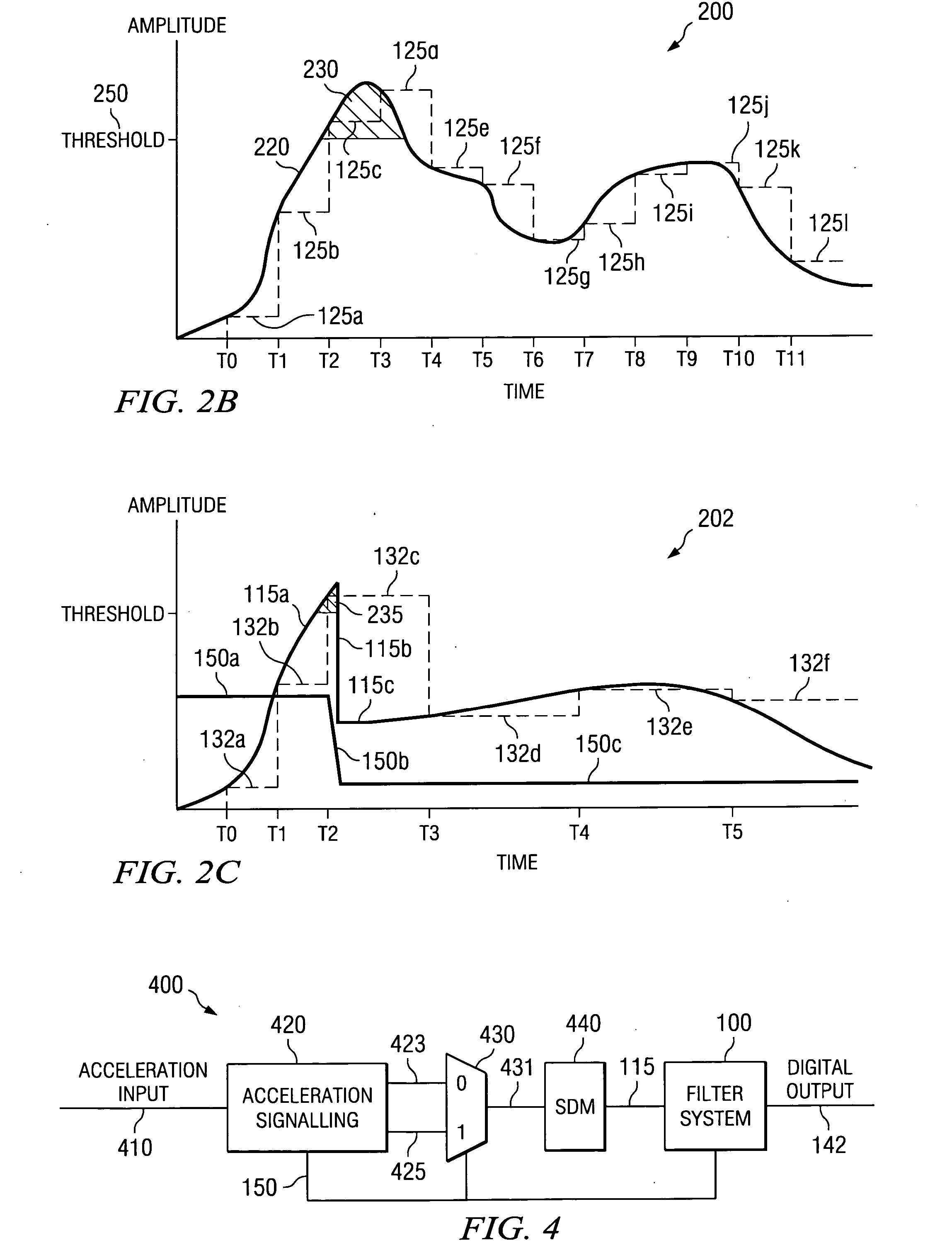
[0022] Various embodiments of the present invention provide circuits, systems and methods for implementing a self test in a slowly varying sensor. Such embodiments include two filters operating in parallel. The two filters receive an input to be monitored, and each of the filters process the input into a respective output. A multiplexer is included that is capable of selecting between the outputs from the respective filters, and providing the selected output for further processing. Where one of the filters operates at a relatively high oversampling rate and the other filter operates at a lower oversampling rate, the multiplexer may be used to select a filter output based upon which oversampling rate best matches the input. In one particular case, one of the filters is a normal operation...


PUM


Abstract

Systems, methods and circuits for implementing a self test in a slowly varying sensor. In one particular case, a circuit is provided that includes two filters operating in parallel. One of the filters is tailored for filtering normal operational signals, and operates at a first oversampling rate. The other filter is tailored for filtering test signals, and operates at a second oversampling rate. The second oversampling rate is generally less than the first oversampling rate. In various cases, the filter tailored for filtering normal operational signals may be programmed for operation across a plurality of oversampling rates.

Description

CROSS-REFERENCE OF RELATED APPLICATION [0001] This application is a Divisional Patent Application of U.S. patent application Ser. No. 11 / 147,812 filed Jun. 7, 2005.BACKGROUND OF THE INVENTION [0002] The present invention is related to systems and methods for monitoring the operation of a sensor, and in particular to systems and methods for testing the operation of a slowly varying sensor. [0003] Various sensors exist that are capable of providing a digital representation of an analog input signal. These sensors are often very accurate and monitor analog input signals that vary slowly in time. To test such a sensor, a slowly varying test signal is typically applied in place of the analog input signal and the digital output of the sensor is compared with a predicted output value. Where the digital output is within a particular range of the predicted output value, the sensor is determined to be functioning properly. Such a test approach can be problematic. For example, to fully test th...

Claims


Application Information

Patent Timeline
Patent Type & Authority Applications(United States)
IPC IPC(8): G01D18/00G01P21/00
CPCG01P21/00
Inventor PITZ, JEANNE KRAYERLEKAN, TEDVINCZE, MICHAEL
Owner TEXAS INSTR INC
Why Eureka
Try Eureka