

Process for producing member having pattern, pattern transfer apparatus, and mold
a technology of pattern transfer and production process, which is applied in the direction of photomechanical equipment, instruments, lithography, etc., can solve the problems of mold and processing failure, mold and mold breakage, mold breakage,
- Summary
- Abstract
- Description
- Claims
- Application Information
AI Technical Summary
Benefits of technology
Problems solved by technology
Method used
Image

Examples
embodiments of production process
(Embodiments of Production Process)
[0063] The production process of a member having a pattern according to an embodiment of the present invention is realized in the following manner.
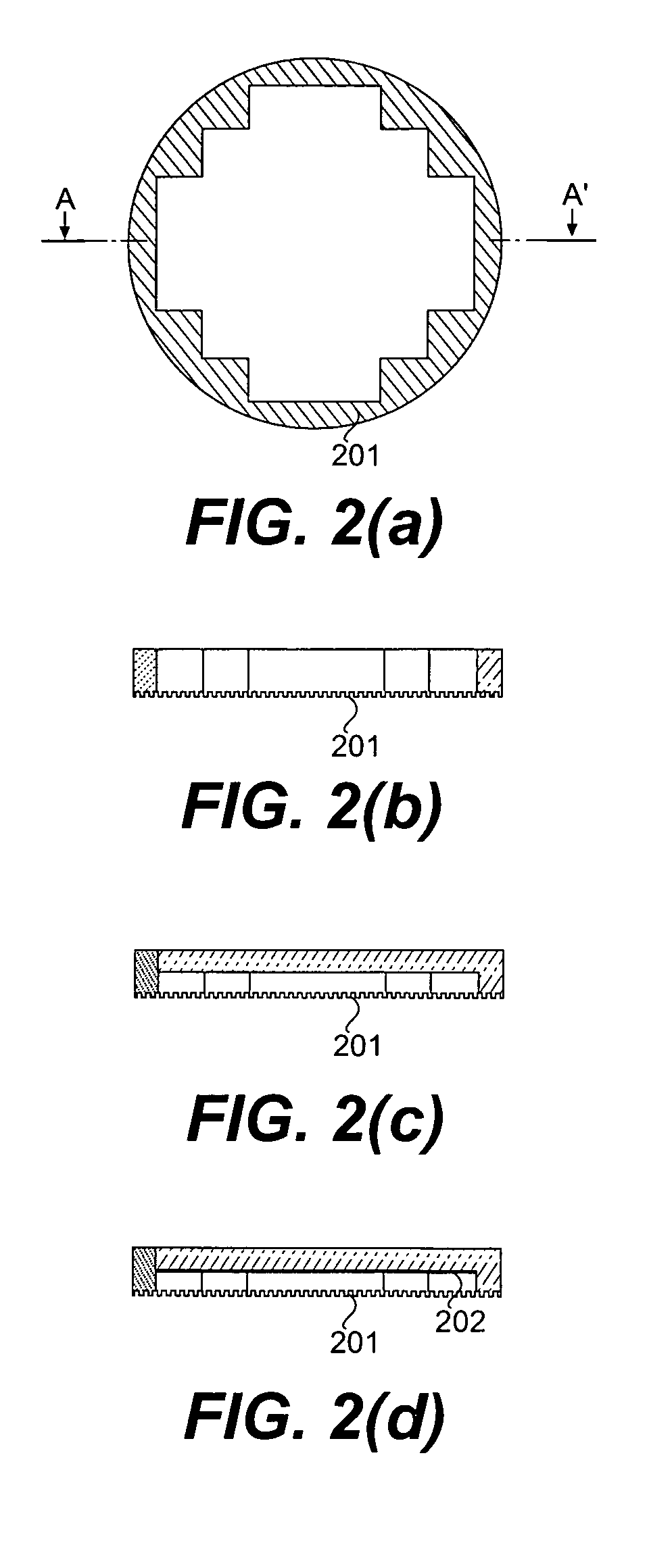
[0064] First of all, a first mold having a first pattern and a second mold having a second pattern including an outer peripheral portion having a shape corresponding to a shape of an outer peripheral portion of the first pattern are prepared. Then, in a peripheral area, of a member to be processed, including an area not enough to transfer an entire first pattern of the first mold (e.g., an area 399 shown in FIG. 3 or FIG. 4(b)), the second pattern (a peripheral pattern 201) is transferred. Further, inside the peripheral area, the first pattern (e.g., a pattern 301 shown in FIG. 3) is transferred. The first pattern may be a pattern group comprising a plurality of pattern units (e,g., each indicated by 301 shown in FIG. 3). In this manner, the process for producing the member having a pattern is realized....
embodiment 1
[0089] In Embodiment 1, a pressure processing apparatus according to the present invention is used.
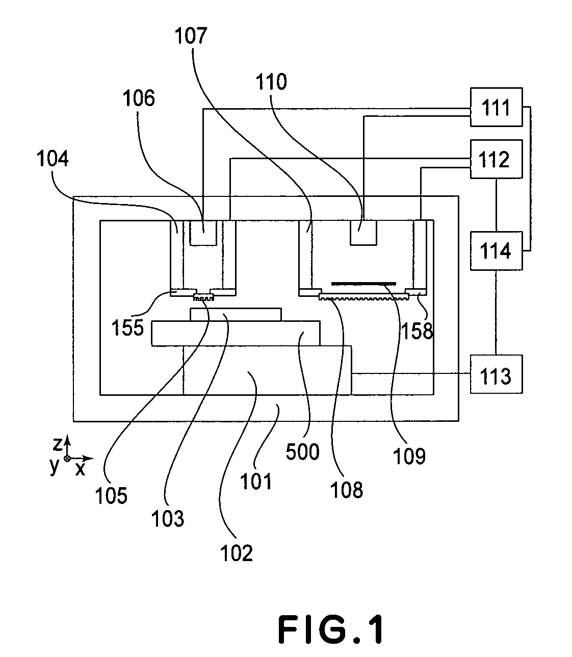
[0090]FIG. 1 shows a constitution of the pressure processing apparatus. Referring to FIG. 1, the apparatus includes a housing 101 for covering the entire apparatus as desired, an xy moving mechanism 102, a work 103 (also referred to as a flat plate-like member or a member to be processed), a pressing mechanism 104, a mold 105, a UV light source 106, a peripheral shot pressing mechanism 107, a peripheral shot mold 108, a light-blocking plate 109, a peripheral shot UV light source 110, an exposure control circuit 111, a pressing control circuit 112, a position control circuit 113, and a process control circuit 114.
[0091] First, an apparatus constitution in this embodiment will be described.
[0092] As shown in FIG. 1, the mold 105 and the peripheral shot mold 108 are disposed at pattern positions so that they are to be opposite to the work, prepared by coating Si wafer with a photocurab...
embodiment 2
[0108] In Embodiment 2, a pressing processing apparatus, different in constitution from that of Example 1, according to the present invention is used.
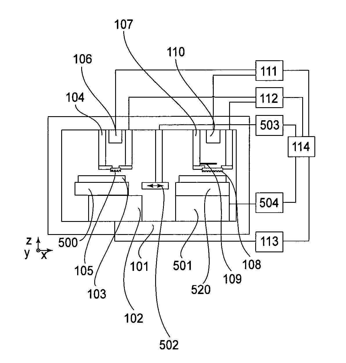
[0109]FIG. 5 shows the constitution of the pressing processing apparatus of this embodiment. In FIG. 5, the same members or means as those in Embodiment 1 are indicated by the same reference numerals, thus omitting explanation for a common constitution.
[0110] The constitution of this embodiment is basically different from that of Embodiment 1 in that a rotation mechanism 501 for rotating the work 103 is disposed immediately below the peripheral shot mold different point is that a conveyance mechanism 502 for conveying the work 103 is disposed between the xy moving mechanism 102 and the rotation mechanism 501 and is controlled by a conveyance mechanism 503. The process control circuit 114 also provides instructions to the conveyance control circuit 503 and the rotation control circuit 504 to effect the processing and receives output d...
PUM
| Property | Measurement | Unit |
|---|---|---|
| Pressure | aaaaa | aaaaa |
| Shape | aaaaa | aaaaa |
| Area | aaaaa | aaaaa |
Abstract
Description
Claims
Application Information