Simplified filter device

a filter device and simplified technology, applied in the field of filter devices, can solve the problems of complex structure, difficult miniaturization, difficult observation of synthetic effects, etc., and achieve the effects of convenient replacement, good filtering efficiency, and easy disassembly/attachmen

a filter device and simplified technology, applied in the field of filter devices, can solve the problems of complex structure, difficult miniaturization, difficult observation of synthetic effects, etc., and achieve the effects of convenient replacement, good filtering efficiency, and easy disassembly/attachmen

US20060273003A1Inactive Publication Date: 2006-12-07ENTEGRIS INC

Image

  • Simplified filter device
  • Simplified filter device
  • Simplified filter device

Examples


first embodiment

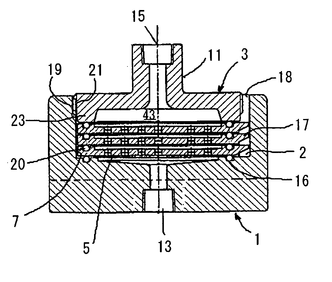
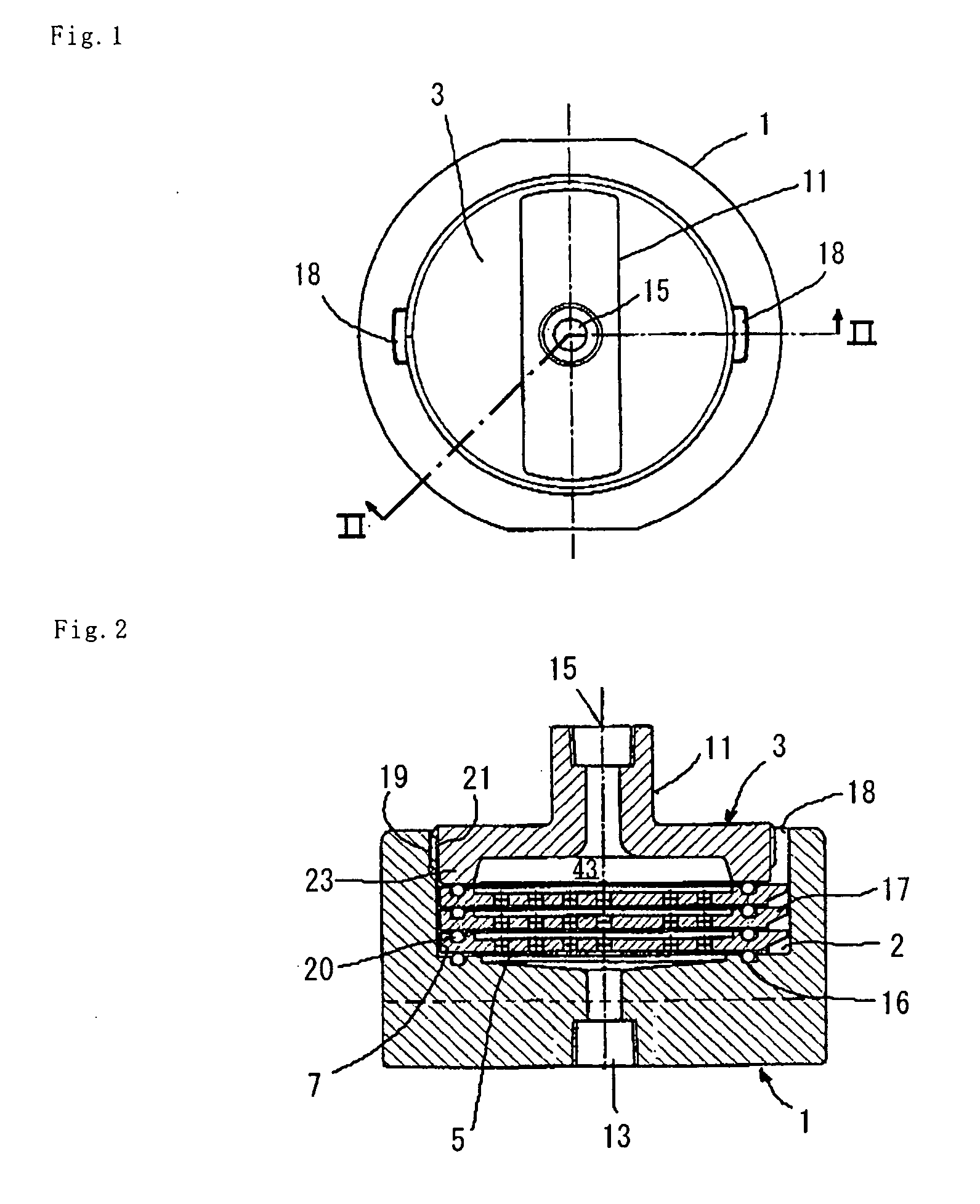
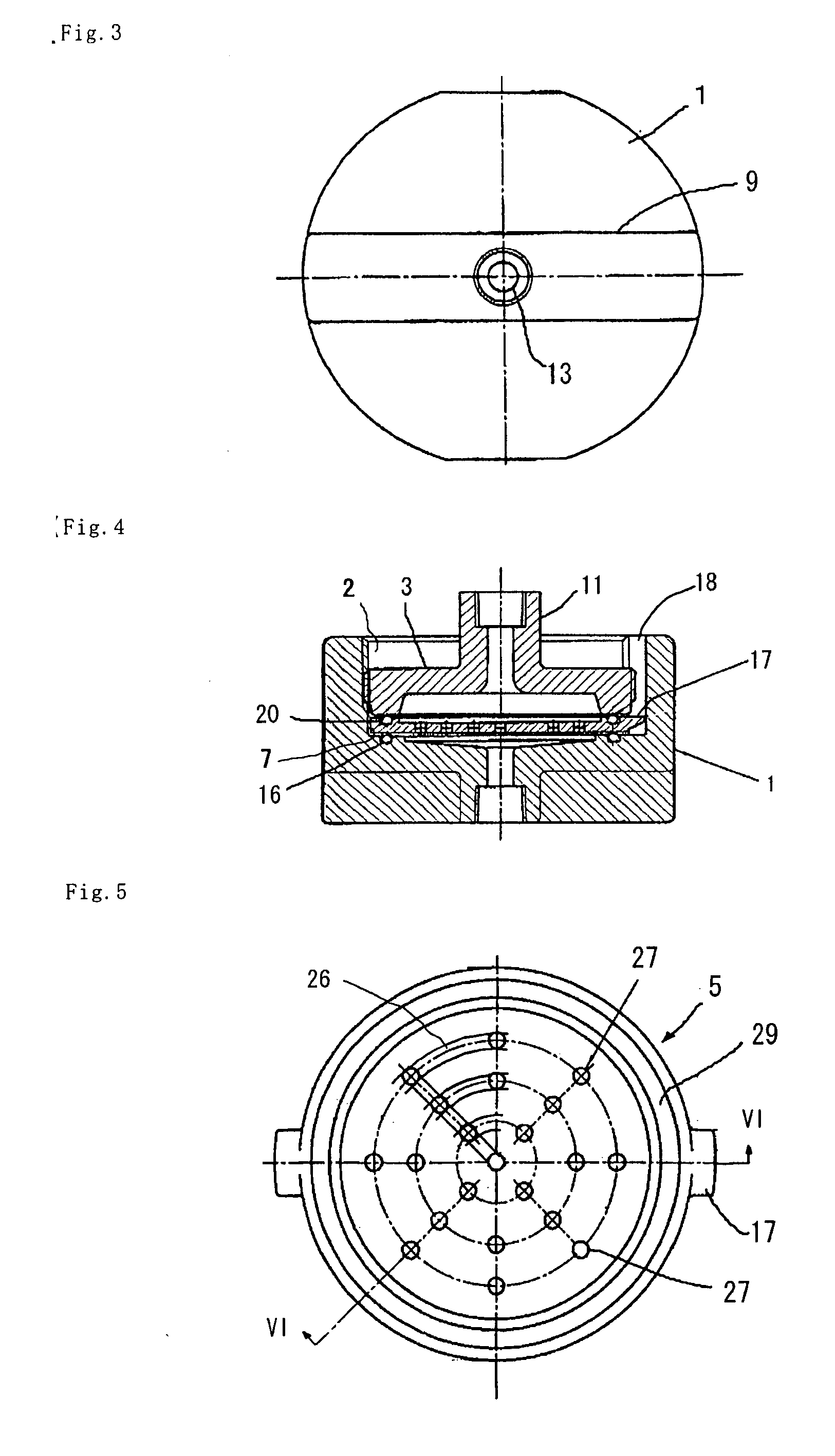
[0045] A simplified type filtering device according to a first embodiment of the present invention will now be explained with reference to FIGS. 1 to 7. The vertical relationship between the components of each figure depends on the convenience of relevant explanation. Namely, the vertical relationship thereof may be inverted, or may be laid horizontal, or a raw liquid supplying port and a filtered liquid discharge port may be inverted from each other.

[0046] If referring to FIGS. 1 to 6 and FIG. 7 that is a partly enlarged view of FIG. 2, the filtering device includes a bowl 1 (or cup) having in its lower surface a discharging port 13 from which a filtered liquid is discharged and having an opening portion 2 (or a recessed portion) in its upper surface, one or more filter plates 5 that are inserted into the opening portion 2 and are supported by a bottom portion of the opening portion, and ahead 3 that is equipped with a shaped-like-an-annulus convex pressing portion 23 which in ord...

second embodiment

[0053] Next, a second embodiment of the present invention will be explained with reference to FIGS. 8 to 14. Although this embodiment is more complex than the filtering device according to the preceding embodiment, it has the advantage that air-tightness and liquid-tightness are easily obtained. In each of these relevant figures, for the members corresponding to those of the filtering device of the first embodiment, there are used the same reference numerals.

[0054] The filtering device according to this embodiment includes a bowl 1 having in its lower surface a discharging port 13 from which a filtered liquid is discharged and having an opening portion 2 or a recessed portion in its upper surface, one or more filter plates 5 that are inserted into the opening portion 2 and are supported by a bottom portion of the opening portion, a head 3 that is equipped with a shaped-like-an-annulus convex pressing portion 23 which in order to air-tightly or liquid-tightly seal the peripheral por...

third embodiment

[0061] Next, a third embodiment of the invention will be explained with reference to FIGS. 15 to 23. Although this embodiment has similarity to the second embodiment that was explained in connection with FIGS. 8 to 14, it differs in the structure of seal portion of the filter plate, the structure of finger engager of the filter plate, and the structure of the locking nut. In each, as well, of these figures, the members corresponding to those of the filtering device according to the second embodiment are denoted by like reference numerals.

[0062]FIG. 15 is a perspective view of a filtering device according to this embodiment, and FIG. 16 is a sectional view taken along a line XVI-XVI of FIG. 15. The filtering device of this embodiment includes a bowl 1 having an opening portion or a recess 2 and a discharging port 13 from which a filtered liquid is discharged, one or more filter plates 5 that are inserted into the opening portion 2 and are supported by a bottom portion of the opening...


PUM

PropertyMeasurementUnit
heightaaaaaaaaaa
circumferenceaaaaaaaaaa
timeaaaaaaaaaa

Abstract

A flow passage for passing a raw liquid to be processed therethrough that is used to test a separation membrane is of the simplest inline type (so-called “inline” type) and is the simplest in construction. In spite thereof, the separation membrane through which the raw liquid is going to be filtered is mounted in a direction substantially perpendicular to the flow passage. In view of this, the object of the present invention is to provide a filtering device with high filtering efficiency, which is used to test the membrane performance of this separation membrane and which enables exchanging its membrane in an easily removably attachable and quick way. The simplified type filtering device that includes a bowl 1 having a discharging port 13 on one side thereof and having on the other side thereof an opening portion 2 in which the separation membrane is loaded, the separation membrane for filtering the raw liquid therethrough, a filter plate 5 by which this separation membrane is fixed to the bowl 1 and which has opening portions for passing the raw liquid or a filtered liquid therethrough, a head 3 having on one side thereof a convex pressing portion 23 that presses the filter plate 5 from one side to prevent the filtered liquid from being leaked and having on the other side thereof a raw liquid supplying opening 15, and means that fastens the head 3 onto the bowl 1 so that the head may be pressed against the bowl 1, such as female and male screws 19, 21 provided with respect to the head 3 and the bowl 1 and screw-engaged with each other, or a separate locking nut 33.

Description

TECHNICAL FIELD [0001] The present invention relates to a filtering device that can serve as a filter for, from a liquid, filtering, separating, or refining a gel and other particulate and the like, and that can simply test the membrane performance of a filtering membrane, separation membrane, or refining membrane (hereinafter referred to as “a separation membrane”) used for that filter. [0002] The filter device according to the present invention can widely be used for filtering a small amount of material in order to make researches and developments, developing a resist, developing medicines, manufacture of beer, manufacture of medicines, purification of photoresist solution in the course of manufacturing a semiconductor or in other fields. BACKGROUND ART [0003] There is a lot of demand for a filtering device that performs filtering, separation, and refinement of a small amount of raw liquid to be supplied. Also, to determine a separation membrane that is optimum to the liquid to be...

Claims


Application Information

Patent Timeline
07 Dec 2006
Publication
US20060273003A1
IPC
B01D39/10; B01D29/05; B01D61/50; B01D63/08; B01D65/00; B01D65/10; B01L3/00
CPC
B01D63/081; B01D63/082; B01D63/087; B01D2313/24; B01D65/10; B01L3/5635; B01D2313/04; B01D65/00
Inventors
SUDO, KAZUNORI; OKA, EIKO