Handle stem and speed indicator

a technology of handle stem and speed indicator, which is applied in the direction of steering devices, instruments, cell components, etc., can solve the problems of affecting the use of the device, and increasing the total weight, so as to achieve the effect of easy replacement of the battery

Inactive Publication Date: 2006-01-03
CATEYE
View PDF29 Cites 12 Cited by
  • Summary
  • Abstract
  • Description
  • Claims
  • Application Information

AI Technical Summary

Benefits of technology

[0012]An object of the present invention is to provide a handle stem and a speed indicator with which a battery can be replaced easily without the need for detachment of the whole of the indicator from the handle stem.

Problems solved by technology

Therefore, the place where attachment / detachment of the indicator is done for replacement of the battery for example is limited to a particular place.
Moreover, if the rider carries tools, the total weight increases which is not preferable for running of the bicycle.
If the entire indicator is detached each time the battery is replaced, the detachment should frequently be done, resulting in a higher possibility of occurrence of break and contact failure of the lead.

Method used


Image

  • Handle stem and speed indicator
  • Handle stem and speed indicator
  • Handle stem and speed indicator

Examples


Embodiment Construction

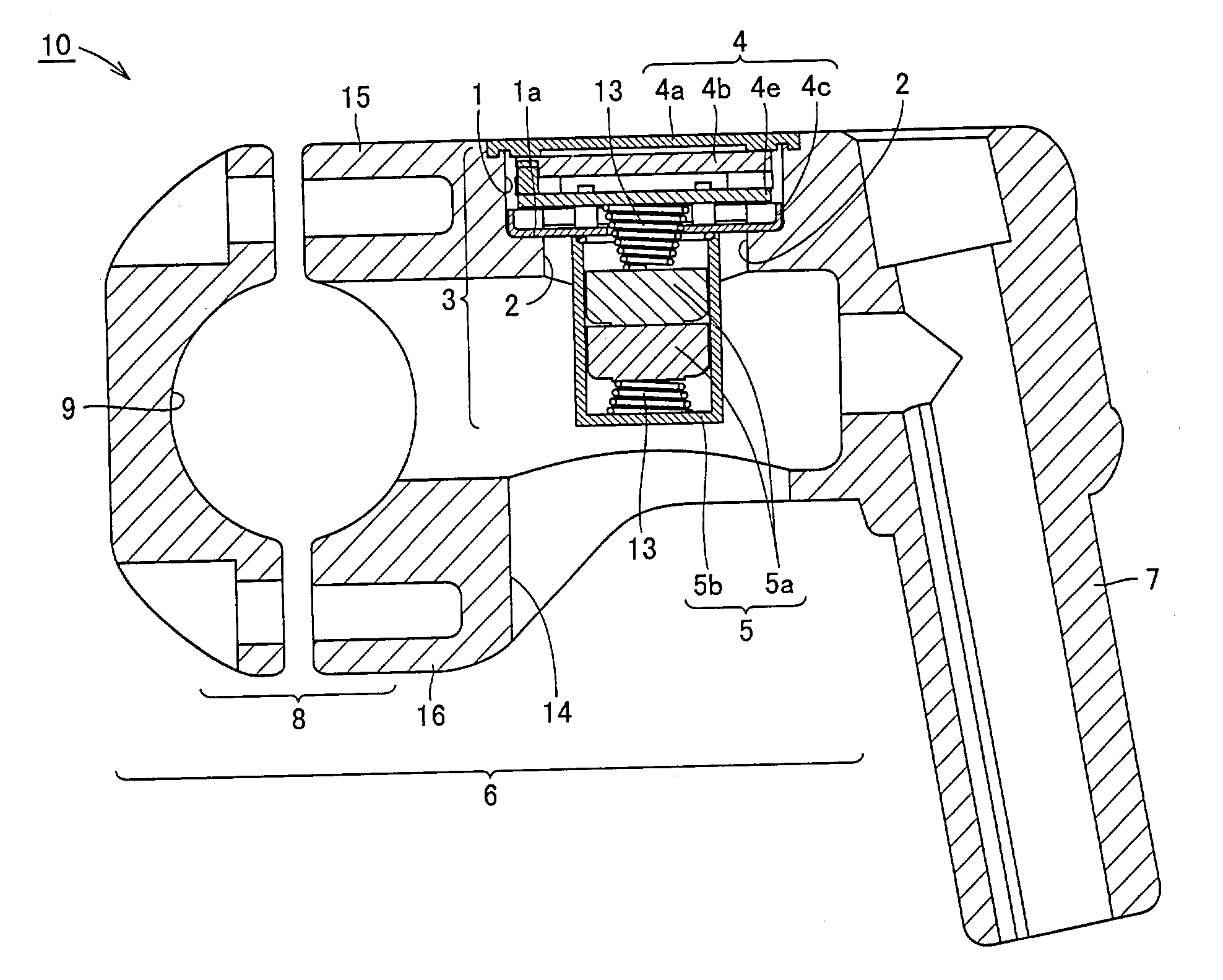
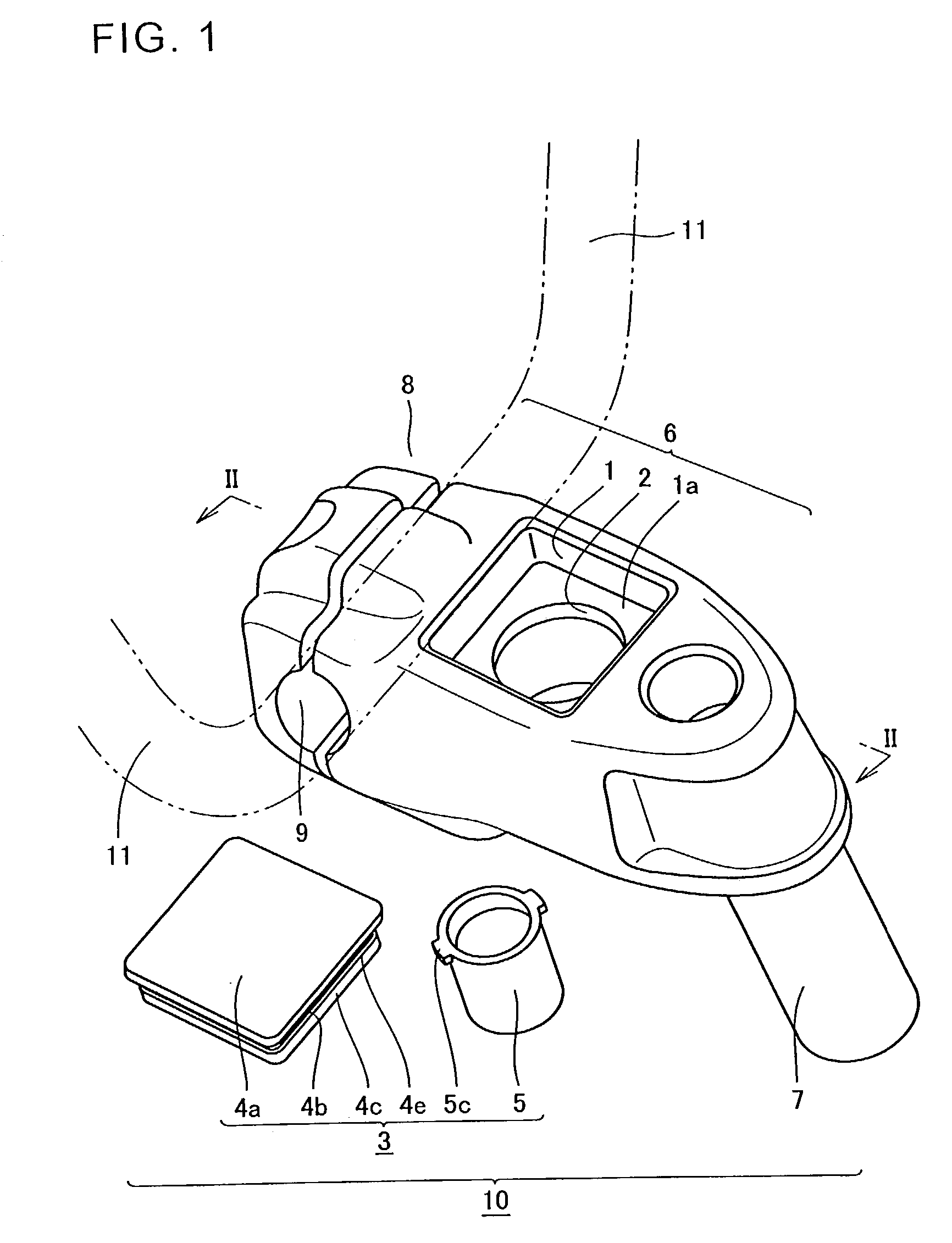
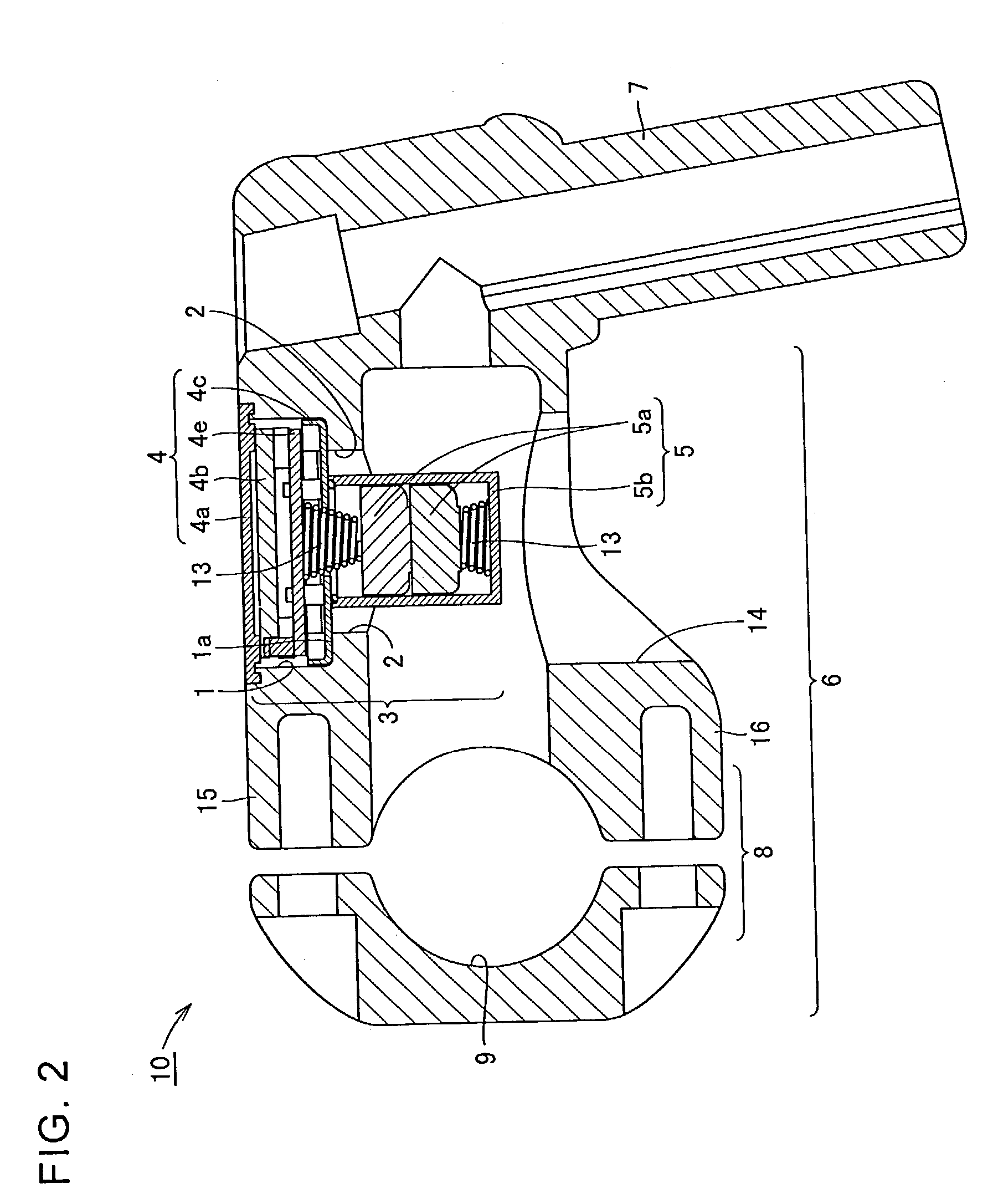
[0031]An embodiment of the present invention is now described in connection with the drawings. FIG. 1 is a perspective view of a handle stem according to an embodiment of the present invention. This handle stem 10 has a forward-projecting part 6 on the upper end of a hollow longitudinal rod 7. On the front end of forward-projecting part 6, a handle-bar holding part 8 having a handle-bar insertion hole 9 therein is placed to hold a handle bar 11. An indicator housing is provided at the center of forward-projecting part 6. The indicator housing is constituted of a housing recess 1 and a through hole 2 opening on a bottom surface 1a of the housing recess. An indicator 3 is constituted of a body 4 formed of a liquid-crystal display and a wiring board, and a battery housing 5. Body 4 has a transparent plate 4a for protection, a liquid-crystal part 4b, circuit board 4e and a bottom 4c insofar as they are seen in FIG. 1. Bottom 4c has an outward-projecting engagement part. Body 4 is fit in...


PUM


Abstract

A handle stem attached to a head tube of a bicycle includes a speed indicator housed in an indicator housing. The indicator is formed of a body including a circuit board and a liquid-crystal display and a battery housing which is detachable from the body. The body is fixed to the indicator housing and accordingly the speed indicator is attached to the handle stem and the battery housing is freely attachable/detachable. The handle stem and the speed indicator are thus obtained with which batteries are easily replaced without detaching the whole of the indicator from the handle stem.

Description

BACKGROUND OF THE INVENTION[0001]1. Field of the Invention[0002]The present invention relates to a handle stem and a speed indicator for bicycles.[0003]2. Description of the Background Art[0004]FIG. 6 shows a front part of a conventional bicycle. On an end of a forward-projecting part of a handle stem 120 of this bicycle, a handle bar 138 is held. At a position which is located on the upper surface of the forward-projecting part of handle stem 120 and is readily visible from the rider, an indicator-housing recess 134 is provided, and an indicator 135 indicating the speed and the like is fit in this indicator-housing recess 134. A lead 149 extending from the indicator passes through a hollow longitudinal rod 121 and a head tube 107 for example to be connected to a sensor 116. Sensor 116 is formed of a device sensing a magnetic field and thus senses a magnetic flux when a small permanent magnet 115 turns to pass near sensor 116. Although lead 149 passes through within longitudinal rod...

Claims


Application Information

Patent Timeline
Patent Type & Authority Patents(United States)
IPC IPC(8): G01P1/02B62J3/00B62J99/00B62K21/12
CPCB62J99/00B62K21/12B62J2099/0033Y10T74/20822B62M2025/003B62J50/225B62J50/21
Inventor KINOSHITA, OSAMU
Owner CATEYE
Why Eureka
Try Eureka