Submerged cross-flow filtration

a technology of cross-flow filtration and submerged membrane, which is applied in the direction of membranes, membrane technology, multi-stage water/sewage treatment, etc., can solve the problems of high operating cost, high packing density modules, and air consumption saving high density modules per membrane area, and still a certain loss of energy during the fluid transfer along the modules

Active Publication Date: 2006-12-07
EVOQUA WATER TECH LLC
View PDF99 Cites 61 Cited by
  • Summary
  • Abstract
  • Description
  • Claims
  • Application Information

AI Technical Summary

Benefits of technology

[0014] Still further aspects of the invention relate to treating or purifying water or a liquid having solids suspended therein. In such aspects, some embodiments of the invention can involve a method of purifying water having solids suspended therein. The method can comprise one or more acts or steps of introducing the water to a membrane module comprising a shell surrounding a plurality of hollow fiber membranes, the shell having a retentate exit port disposed adjacent to at least one of a lower potting head and an upper potting head, introducing a scouring fluid into a volume enclosed by the shell, the scouring fluid comprising a gas, a liquid, or a mixture thereof, and withdrawing permeate through the hollow fiber membranes to produce purified water.

Problems solved by technology

The gas / air consumption, required to scrub the membranes, however, was found to be a dominant portion in operating energy used in such a filtration process which resulted in high than expected operating costs.
The use of high packing density modules also saves air consumption per membrane area.
Therefore there is still a certain loss of energy during the fluid transfer along the modules.
Because more energy is required to create a high shear force to effectively clean the membrane, the application of the cross-flow filtration process is now limited, mainly to tubular membrane filtration applications.

Method used


Image

  • Submerged cross-flow filtration
  • Submerged cross-flow filtration
  • Submerged cross-flow filtration

Examples


example

[0072] A standard submerged membrane filtration module, containing 2,200 fibers, was tested to filter mixed liquor from the bioreactor. Without the enclosure, an air flow-rate of 3 m3 / hr was required to achieve a stable filtration performance at a flux of 30 L / m2 / hr. When an enclosure was used, the air requirement was dropped to 2 m3 / hr to achieve a similar result, a saving of air by 33%.

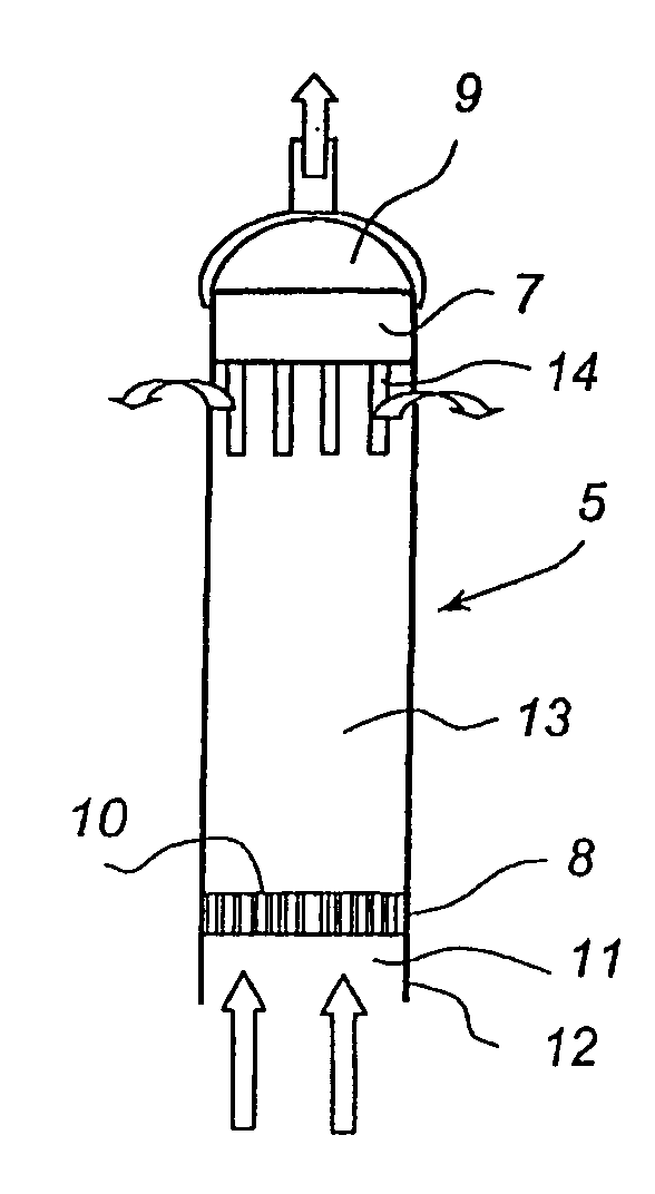
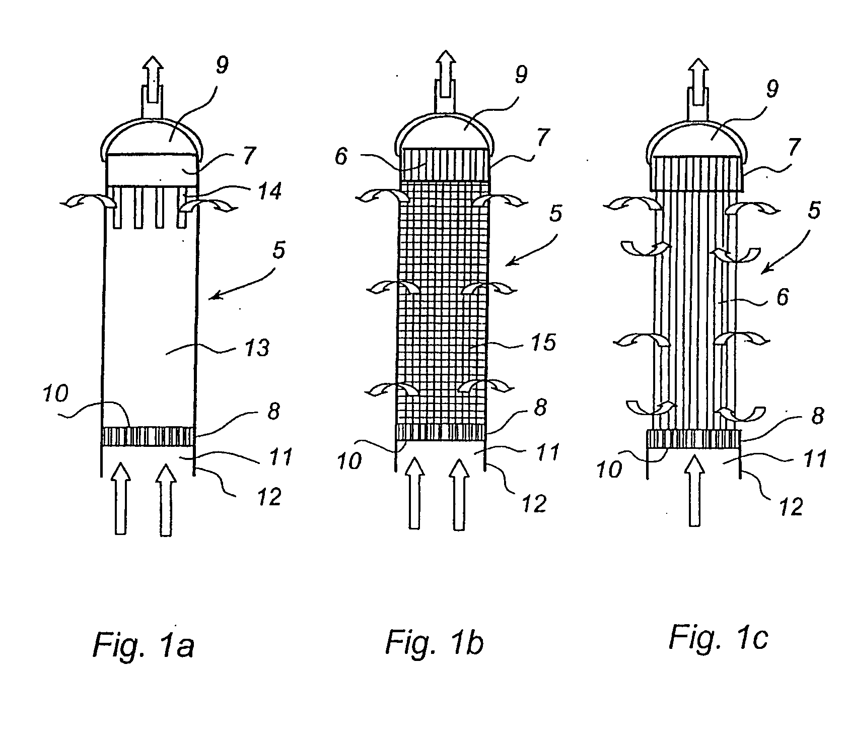
[0073] The filtration process provided by the invention is different from the conventional cross-flow filtration process, as the gas scouring generates more efficient cleaning with less energy in the submerged cross-flow filtration system. The enclosure used is of a low cost and needs little pressure tolerance.

[0074] Thus, the submerged cross-flow filtration system described here combines the low capital cost of the submerged system with the efficiency of the cross-flow process.

[0075] While the inventive concept has been illustrated in the embodiments and examples with reference to hollow fiber m...


PUM


Abstract

A membrane filtration module having a plurality of permeable, hollow membranes is disclosed. In use, a pressure differential is applied across the walls of the permeable, hollow membranes when immersed in a liquid suspension containing suspended solids. Some of the liquid suspension passes through the walls of the membranes to be drawn off as clarified liquid or permeate, and at least some of the solids are retained on or in the permeable, hollow membranes or otherwise as suspended solids within the liquid suspension. The module has a shell or similar structure that at least partially surrounds the membrane module and substantially effects retaining at least portion of fluid flowed into the membrane module.

Description

CROSS-REFERENCE TO RELATED APPLICATIONS [0001] This application claims priority under 35 U.S.C. § 119(e) to U.S. Provisional Application Ser. No. 60 / 684,710, entitled “HYBRID TANGENTIAL FLOW MEMBRANE MODULE FOR IMMERSED WATER AND WASTEWATER APPLICATION,” filed on May 20, 2005, which is incorporated herein by reference in its entirety. [0002] Foreign priority benefits are claimed under 35 U.S.C. § 119(a)-(d) or 35 U.S.C. § 365(b) of International Application No. PCT / AU2005 / 001662, filed Oct. 26, 2005, which claims priority to Australian Application No. 2004906322, filed on Nov. 2, 2004, each of which is also incorporated herein in its entirety.BACKGROUND OF THE INVENTION [0003] 1. Field of Invention [0004] The present invention relates to membrane filtration systems and, more particularly, to submerged membrane filtration systems and their operation. [0005] 2. Discussion of Related Art [0006] Submerged membrane filtration process with air scrubbing emerged in the 1980's. The driving ...

Claims


Application Information

Patent Timeline
Patent Type & Authority Applications(United States)
IPC IPC(8): B01D65/02
CPCB01D61/18B01D63/024B01D63/043B01D65/08B01D2313/23B01D2321/185B01D2321/2016C02F1/444B01D2315/06
Inventor ZHA, FUFANGGANZI, GARY C.BECK, THOMAS W.
Owner EVOQUA WATER TECH LLC
Why Eureka
Try Eureka