Oil-based sludge separation and treatment system

a technology of oil-based sludge and separation and treatment system, which is applied in the direction of separation process, multi-stage water/sewage treatment, other chemical processes, etc., can solve the problems of ineffective disk stack centrifuge and ineffective non-emulsified water and oil blend

Inactive Publication Date: 2006-12-07
MI
View PDF21 Cites 12 Cited by
  • Summary
  • Abstract
  • Description
  • Claims
  • Application Information

AI Technical Summary

Problems solved by technology

Traditionally, disk stack centrifuges have been used to condition slope oil or sludge, but they are only effective for non-emulsified water and oil blends.
However, due to the existence of the in-situ natural emulsifiers, production sludges are characterized by strong water-in-oil emulsions.
For such blends, a disk stack centrifuge is ineffective.

Method used


Image

  • Oil-based sludge separation and treatment system
  • Oil-based sludge separation and treatment system
  • Oil-based sludge separation and treatment system

Examples


Embodiment Construction

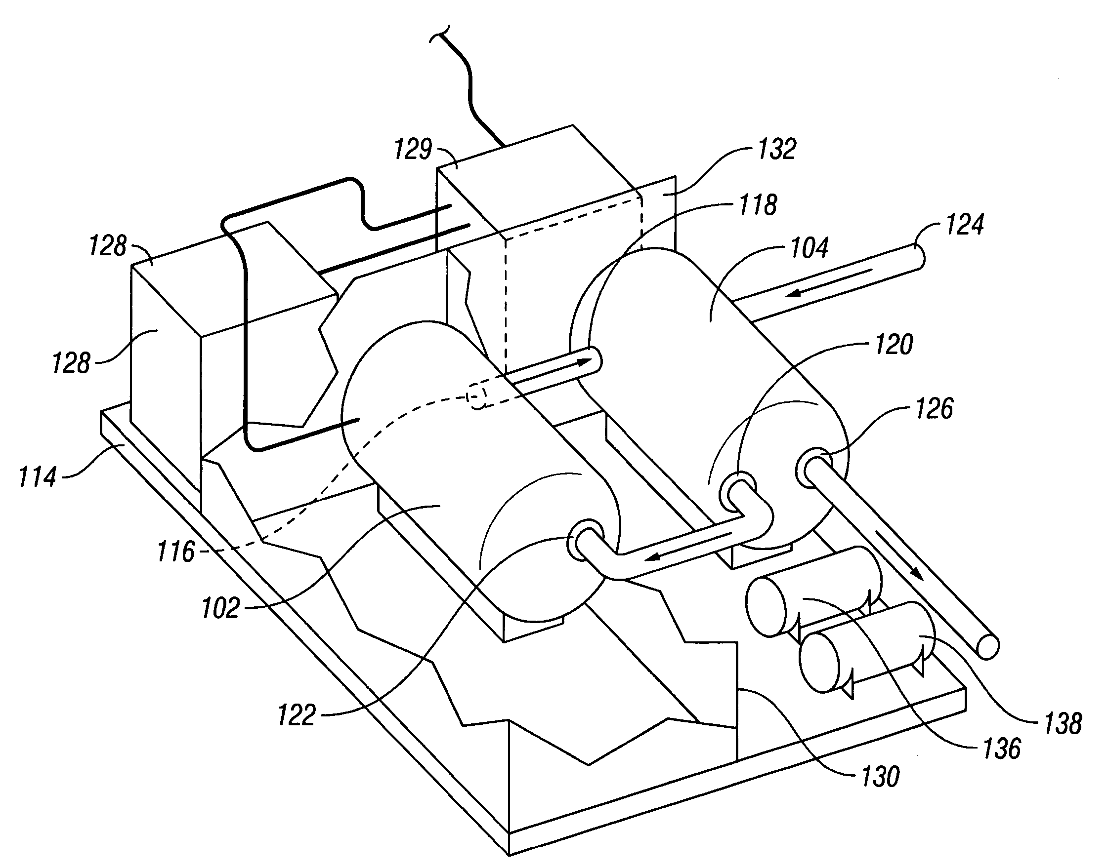
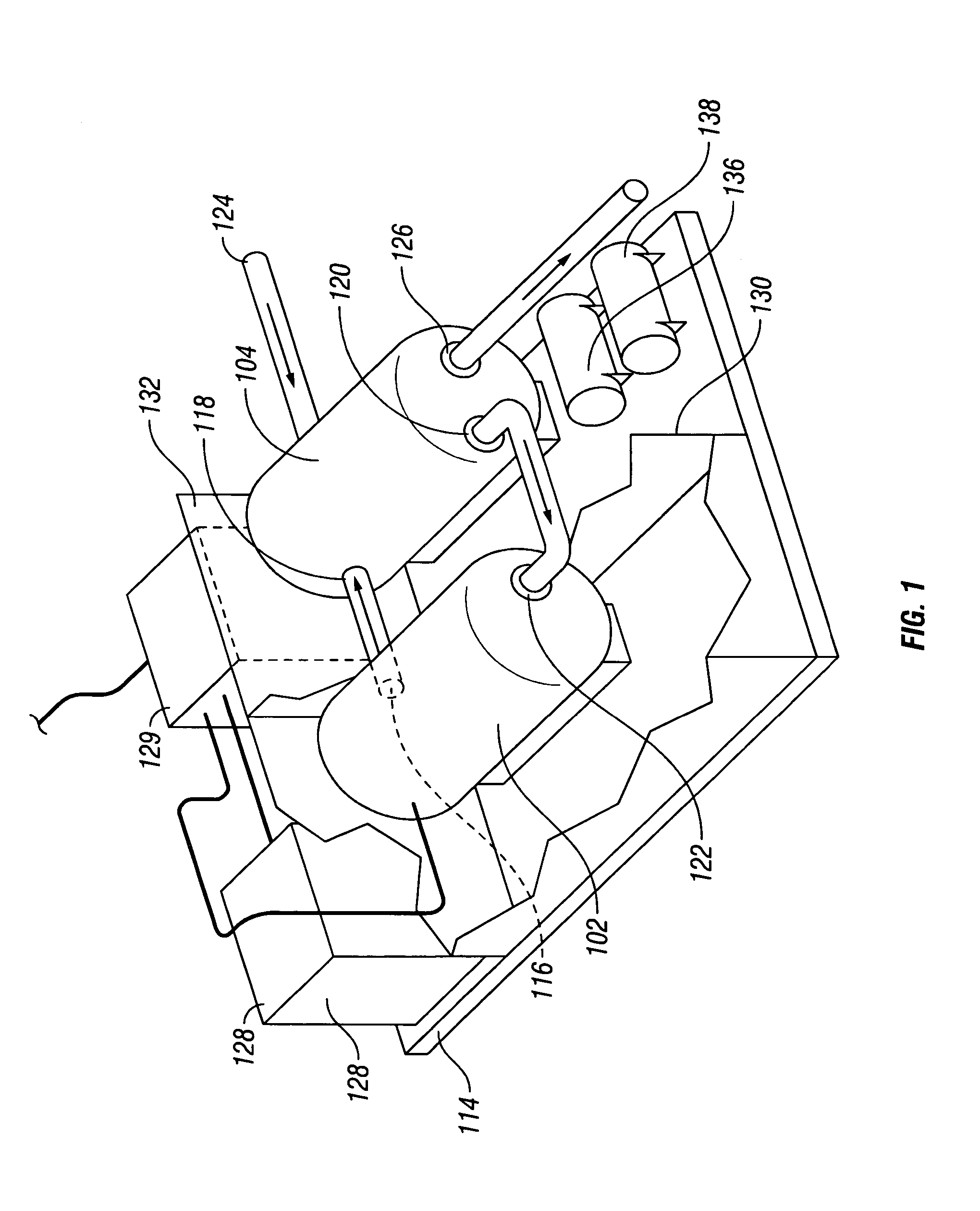
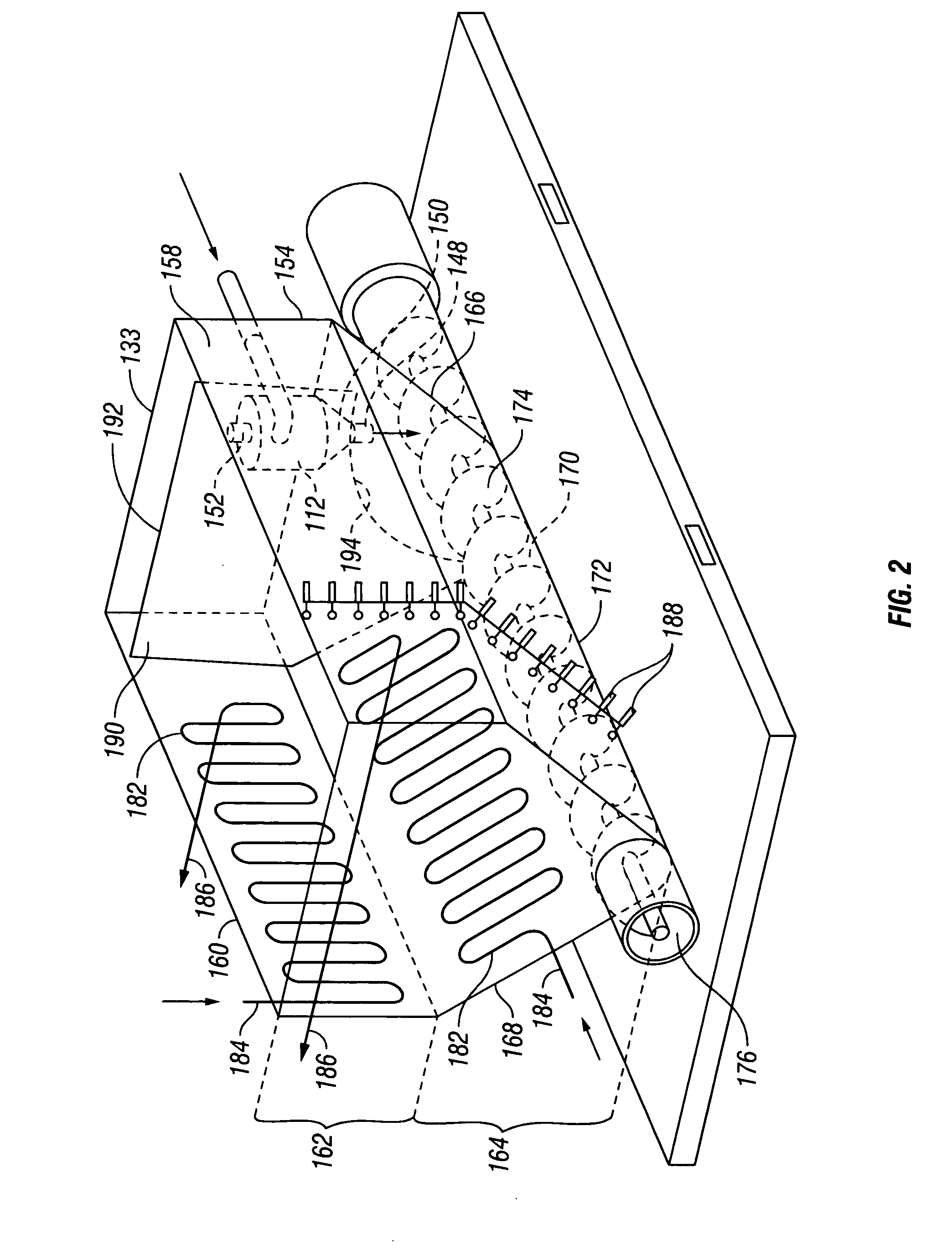
[0014] The claimed subject matter relates to a modular apparatus 100, shown in FIG. 3, for treating oil-based sludge and a method for using the apparatus. The apparatus includes three primary sections, a heating section, a mixing section, and a separation and settling section. The heating section, shown in FIGS. 1, 3, and 5, includes a boiler 102 and a heat exchanger 104. The mixing section, shown in FIG. 3 and schematically in FIG. 6, includes mixers 106, 108. The separation and settling section, shown in FIGS. 2 and 3, includes a tank 110 within which a hydrocyclone 112 is located. As depicted in FIG. 3, in one embodiment, all three sections are co-located on a skid 114, making the entire apparatus 100 easily transportable.

[0015] Referring to FIGS. 1 and 5, the heating section includes the boiler 102 and the heat exchanger 104. The boiler 102 is used to provide steam to the heat exchanger 104. Steam, heated in the boiler 102 is directed from a first steam outlet 116 to a first st...


PUM

PropertyMeasurementUnit
pressureaaaaaaaaaa
temperatureaaaaaaaaaa
timeaaaaaaaaaa

Abstract

An apparatus for treating oil-based sludge includes a boiler, a heat exchanger having a circulatory steam path in fluid communication with the boiler and a sludge path receiving sludge, a plurality of serially-aligned mixers in fluid communication with the sludge path of the heat exchanger, a separation tank in fluid communication with the plurality of mixers, and wherein the separation tank includes a tank having a plurality of walls, a hydrocyclone mounted within the tank receiving sludge from the plurality of mixers, wherein the hydrocyclone includes a solids outlet directing a solids component towards a bottom portion of the tank and a fluid outlet directing a fluid component into the tank, a means for conveying separated solids along the bottom portion of the tank to a solids outlet, and a plurality of fluid outlets vertically located along a tank wall, wherein each outlet includes a valve providing selective fluid communication from the tank.

Description

[0001] This application claim priority to U.S. Provisional Patent Application Ser. No. 60 / 682,472 filed on May 19, 2005 entitled, “Oil-Based Sludge Separation and Treatment System” incorporated herein by reference for all purposes.BACKGROUND OF INVENTION [0002] The term “sludge” is a generic description of an oily waste stream that typically has a high solids content and varying quantities of hydrocarbons and water. Certain sludges, such as those generated in the production of various hydrocarbon products, includes vessel sludges, tank bottom sediments and emulsions from water treatment systems. Waste sludge resulting from producing oil and gas wells, for example, is often stored in open pits where it may be left for considerable time before being treated. During such aging periods, the sludge undergoes chemical changes including the effects of weathering and volatilization. It is desirable to treat the sludge to reduce the risk of contamination of the surrounding area and to recove...

Claims


Application Information

Patent Timeline
Patent Type & Authority Applications(United States)
IPC IPC(8): C02F1/38
CPCB01D21/009B01D2221/04B01D21/2411B01D21/2444B01D21/2461B01D21/26C02F1/02C02F1/38C02F1/40C02F11/127C02F11/14C02F11/18C02F2101/32C02F2101/325B01D21/10B01D21/267
Inventor IVAN, CATALIN
Owner MI
Why Eureka
Try Eureka