Technique for compensation of transmit leakage in radar receiver

a technology for transmitting leakage and radar receiver, which is applied in the direction of reradiation, measurement devices, instruments, etc., can solve the problems of limited prior attempts to reduce signal leakage into the receiver

Active Publication Date: 2006-12-07
RAYTHEON CO
View PDF7 Cites 125 Cited by
  • Summary
  • Abstract
  • Description
  • Claims
  • Application Information

AI Technical Summary

Problems solved by technology

Prior attempts to reduce signal leakage into the receiver have been limited to multi-frequency simultaneous transmit and receive (STAR) systems where a separation between transmit and receive frequencies exists.

Method used


Image

  • Technique for compensation of transmit leakage in radar receiver
  • Technique for compensation of transmit leakage in radar receiver
  • Technique for compensation of transmit leakage in radar receiver

Examples


Embodiment Construction

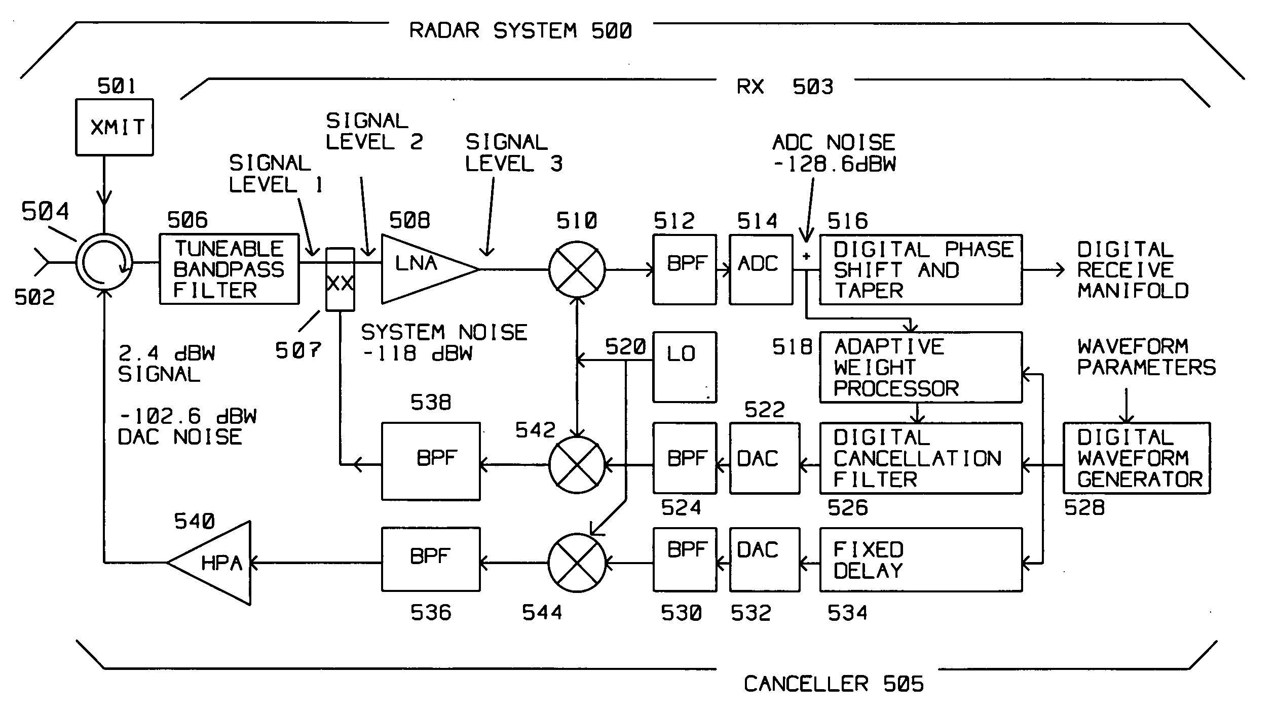
[0016] The present invention describes an apparatus and method for canceling or reducing the effects of signal leakage from a radar transmitter into a radar signal receiver.

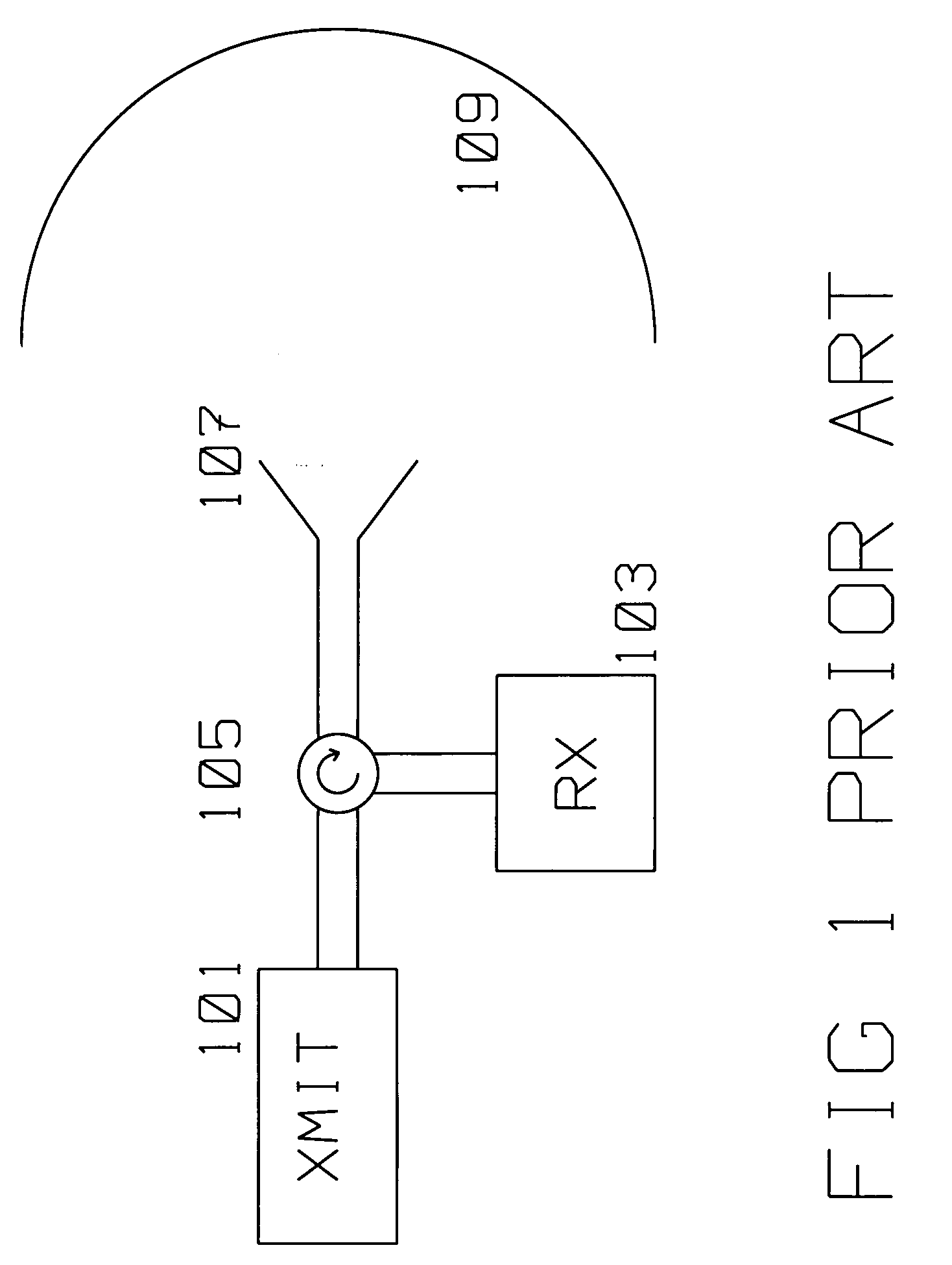
[0017]FIG. 1 shows a typical configuration of the prior art. Transmitter 101 is switched using circulator (switch) 105 to antenna 107 during radar signal transmission. Circulator (switch) 105 decouples receiver 103 during radar signal transmission. Radome 109 protects antenna 107 from rain and other influences. Receiver 103 is very sensitive as it has to detect radar signal reflections returned from a target miles away. Thus, the energy from transmitter 101 is always kept separate from Receiver 103 as Receiver 103 may be damaged or saturated by the powerful transmit signal from transmitter 101. The power to be detected by receiver 103, PR is generally proportional to: PR=PT⁢σR41

[0018] where PT is transmitter 101 power, a is target crossection reflecting the power transmitted from transmitter 101 from a distance...


PUM


Abstract

A radar system (500) radiates a radar transmit signal, has a radar signal receiver (503) and a canceller (505) for canceling leakage of the transmit signal into the radar signal receiver (503). The canceller (505) comprises a digital waveform generator (528) for generating a first digital signal converted to an analog waveform. The analog waveform is amplified after a fixed delay (534) to generate a first cancellation signal input into a circulator (504). The circulator combines the first cancellation signal with the leakage to generate a first corrected signal. A summer (507) combines the first corrected signal from the circulator with a second cancellation signal to generate a second corrected signal. The second cancellation signal is generated by a digital cancellation filter (526). The digital cancellation filter (526) has as an input the first digital signal from the digital waveform generator (528). The digital cancellation filter (526) is controlled using weight adjustments computed by an adaptive weight processor (518). The adaptive weight processor (518) samples the second corrected signal and computes the weight adjustments to optimize the second cancellation signal.

Description

BACKGROUND OF THE INVENTION [0001] 1. Field of Invention [0002] This invention is in the field of leakage cancellation of a radar transmit signal into a receiver. [0003] 2. Description of the Related Art [0004] A radar transmits a transmit signal as well as receives a return radar signal. By necessity, the transmit signal is far more powerful than the received signal, as the received signal is reflected by the target and attenuated by a factor of (Range to Target)4. Because of this attenuation of the reflected return radar signal, very sensitive receivers are employed to assure its reception. [0005] Historically, the sensitive receiver is switched off, or decoupled from the microwave path while a radar signal is being transmitted. This decoupling during transmit time avoids saturating or damaging the sensitive receiver by the presence of the overwhelmingly powerful transmitter output. Some applications however, require both the transmit signal and receiver to be operating concurrent...

Claims


Application Information

Patent Timeline
Patent Type & Authority Applications(United States)
IPC IPC(8): G01S13/00G01S7/28
CPCG01S7/038G01S7/352H04B1/525G01S2007/356G01S13/32G01S7/356
Inventor KRIKORIAN, KAPRIEL V.ROSEN, ROBERT A.
Owner RAYTHEON CO
Why Eureka
Try Eureka