
Antenna device having rotatable structure
- Summary
- Abstract
- Description
- Claims
- Application Information
AI Technical Summary
Benefits of technology
Problems solved by technology
Method used
Image

Examples
Embodiment Construction
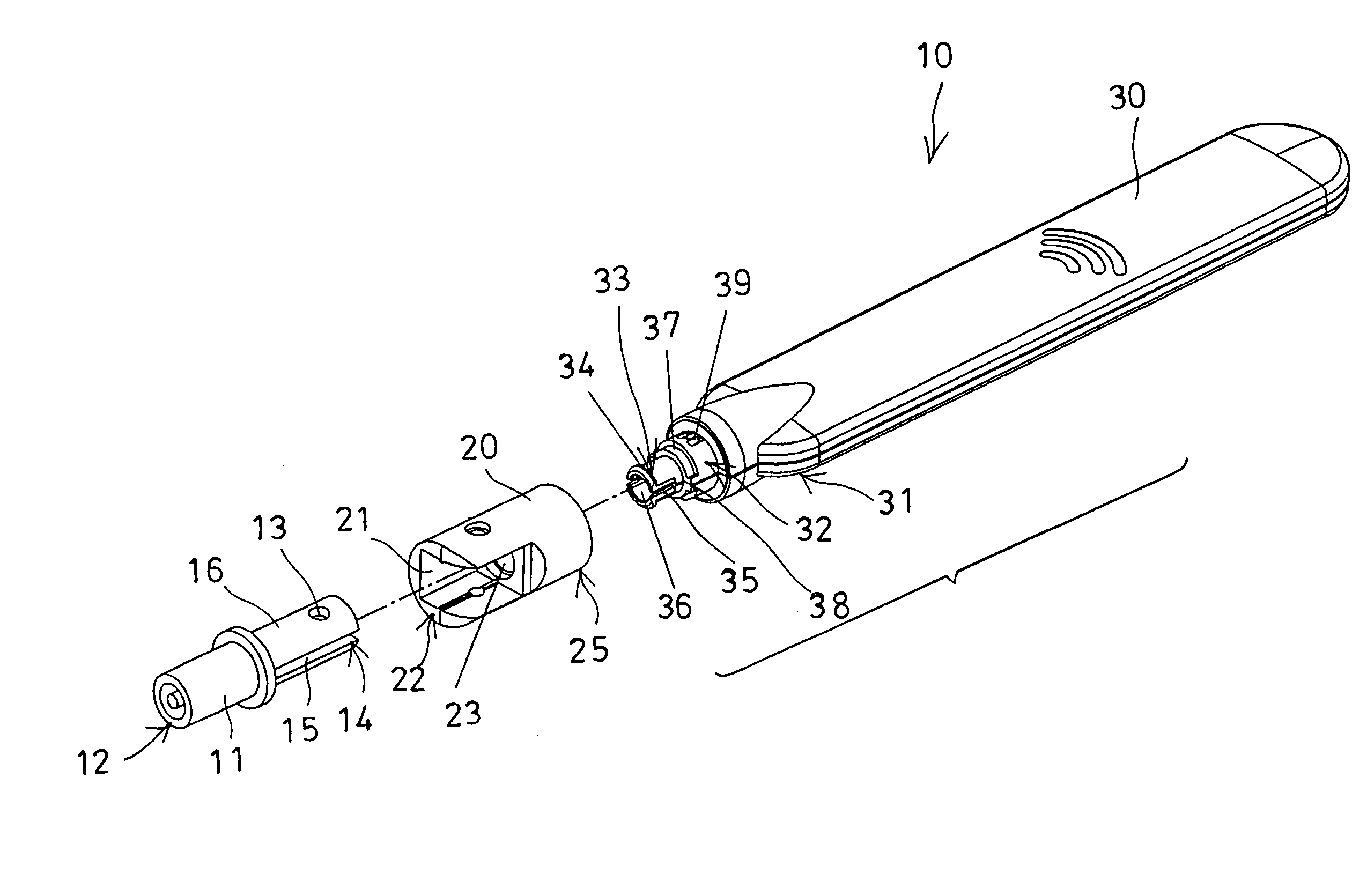
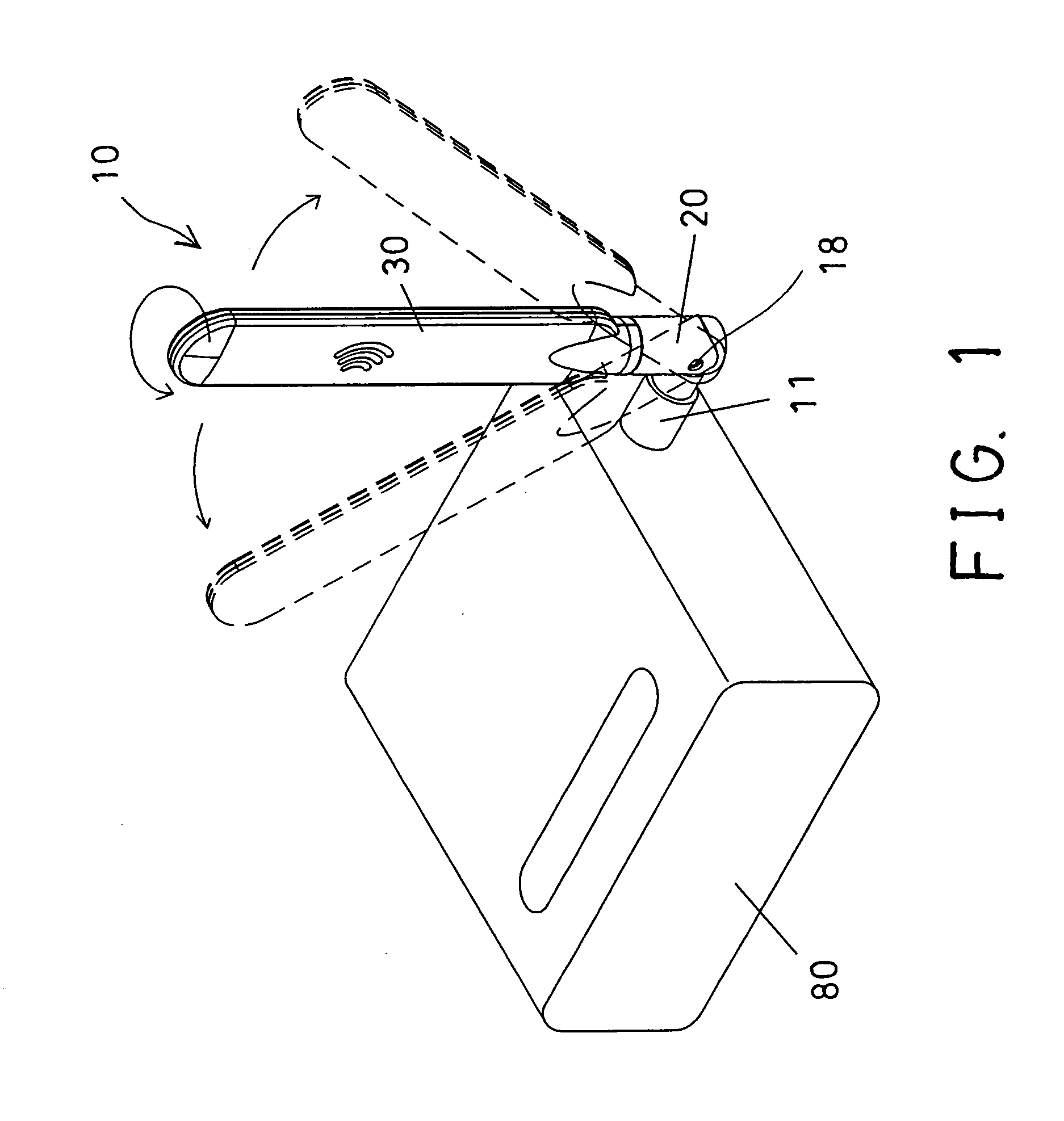
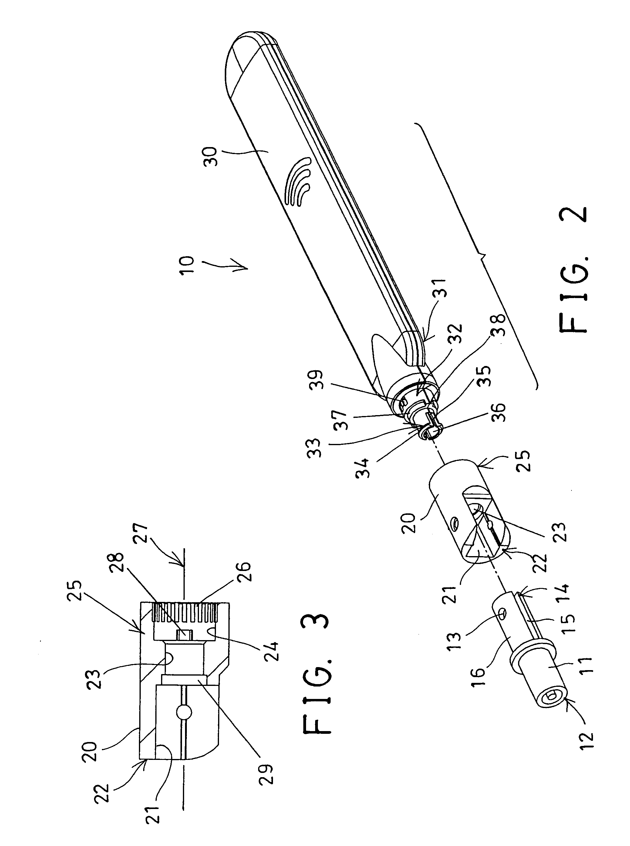
[0020] Referring to the drawings, and initially to FIGS. 1 and 2, an antenna device 10 in accordance with the present invention is provided or arranged for pivotally or rotatably attached to a telecommunicating facility or electric facility or other support objects or devices 80, and comprises a coupler 11 including one end 12 for pivotally or rotatably plugging or attaching to the telecommunicating facility or support device 80, and including an orifice 13 formed in the other end 14 thereof, and preferably further including one or more slots 15 formed in the other end 14 thereof to form one or more spring arms 16.
[0021] A connector 20 includes a chamber 21 formed therein, such as formed in one end 22 thereof, for rotatably receiving or attaching the other end 14 of the coupler 11, and may be pivotally or rotatably coupled to the coupler 11 with a pivot axle 18 (FIG. 1), to allow the connector 20 to be rotated relative to the coupler 11 about the pivot axle 18. The connector 20 inc...
PUM
 Abstract
Description
Claims
Application Information