Directional screen and image projection system

a projection system and directional screen technology, applied in the direction of projectors, instruments, bundled fibre light guides, etc., can solve the problems of difficult to display a clear image in a bright room, and achieve the effects of reducing cost, clear image, and wounding or folding

Inactive Publication Date: 2006-12-07
YAMAUCHI NAOFUMI
View PDF5 Cites 112 Cited by
  • Summary
  • Abstract
  • Description
  • Claims
  • Application Information

AI Technical Summary

Benefits of technology

[0014] Alternatively, the screen of the present invention has multiple fibrous protrusions each having light reflectivity formed on the base material, the multiple fibrous protrusions being slanted in the direction of external light. As a result, the screen functions to reflect or transmit light from a specific direction and to absorb light from a direction except the specific direction. To be specific, fibrous protrusions each having a high light reflectance are densely formed on the base material while the protrusions are slanted in the direction of external light. With such constitution, light from a projector is reflected on the surface of each fibrous protrusion. In addition, external light such as illumination light enters a gap between two adjacent fibrous protrusions, and is repeatedly reflected on the side surfaces of the fibrous protrusions to be absorbed. Accordingly, the screen is hardly affected by the external light, and can display a clear image even in a bright room.
[0015] In addition, a light absorbing layer is formed on the surface of the base material of the screen. The formation reduces an influence of external light incident on the side surface of each fibrous protrusion on the screen because the external light is guided to and absorbed by the surface of the base material.
[0016] Furthermore, the base material is a black cloth obtained by knitting fibers each impregnated with a black pigment or dye. After white fibers have been implanted on the black cloth, the white fibers are aligned with a predetermined direction to form the fibrous protrusions. As a result, the screen of the present invention can be produced at a reduced cost, and is so flexible that it can be wound or folded.
[0017] In addition, the screen is formed by obliquely embedding and fixing the fibrous protrusions composed of the white fibers in a light absorbable resin base material

Problems solved by technology

Accordingly, the screen has a problem in that it is

Method used


Image

  • Directional screen and image projection system
  • Directional screen and image projection system
  • Directional screen and image projection system

Examples


example 1

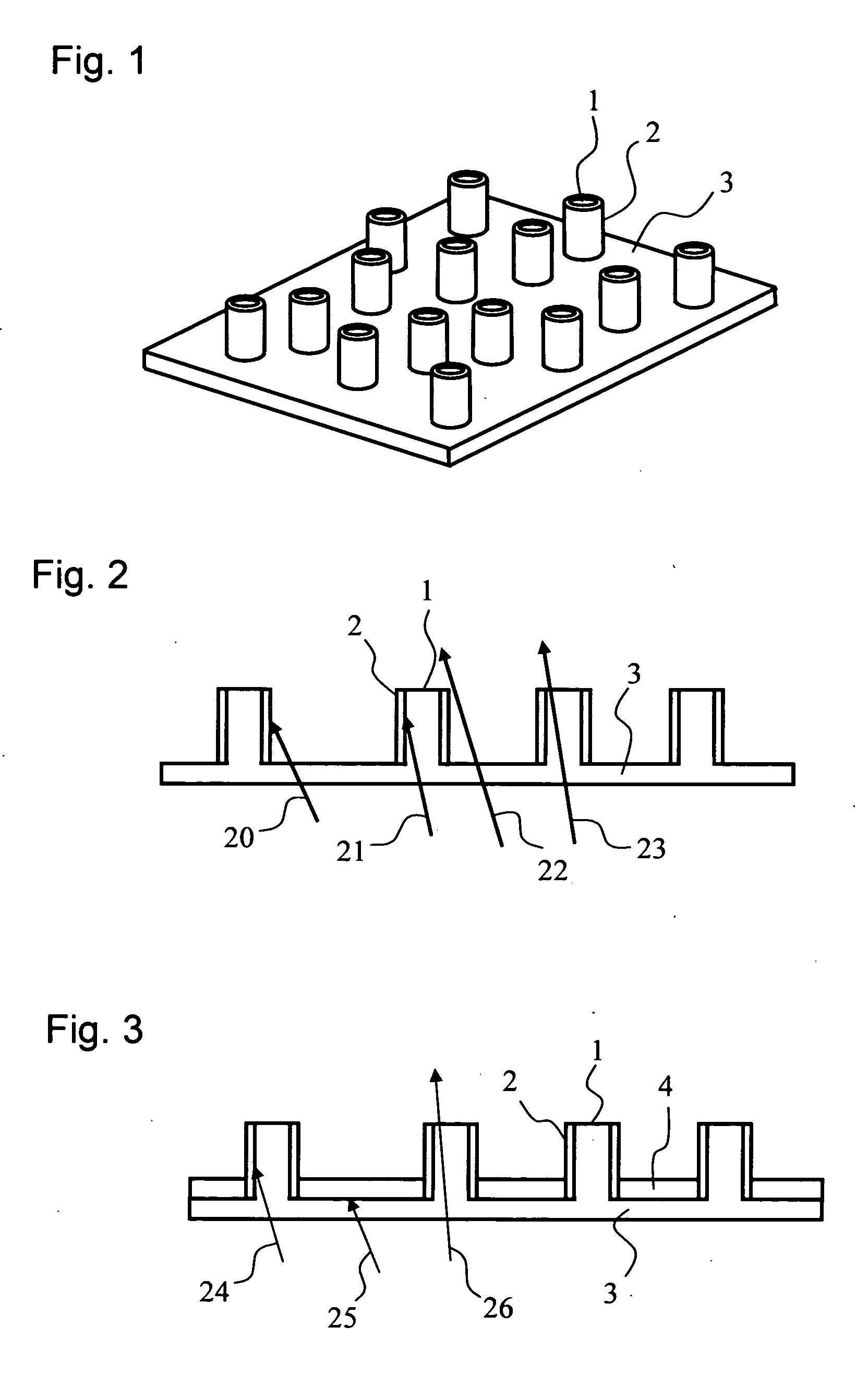
[0050]FIG. 1 schematically shows a perspective drawing explaining the basic constitution of a screen of this example. As shown in the figure, the screen of this example has multiple protrusions 1 as protrusion structures formed on the base material 3. A light absorbing layer 2 is formed on the side surface of each of the protrusions 1. Here, the protrusions 1 each have a transparent columnar structure. The upper surface shape of each of the protrusions 1 is a circular shape, but is not necessarily a circular shape. The upper surface shape may be an elliptical shape, a polygonal shape, or an irregular shape. In this example, a circular upper surface shape that can be most easily produced is exemplified.

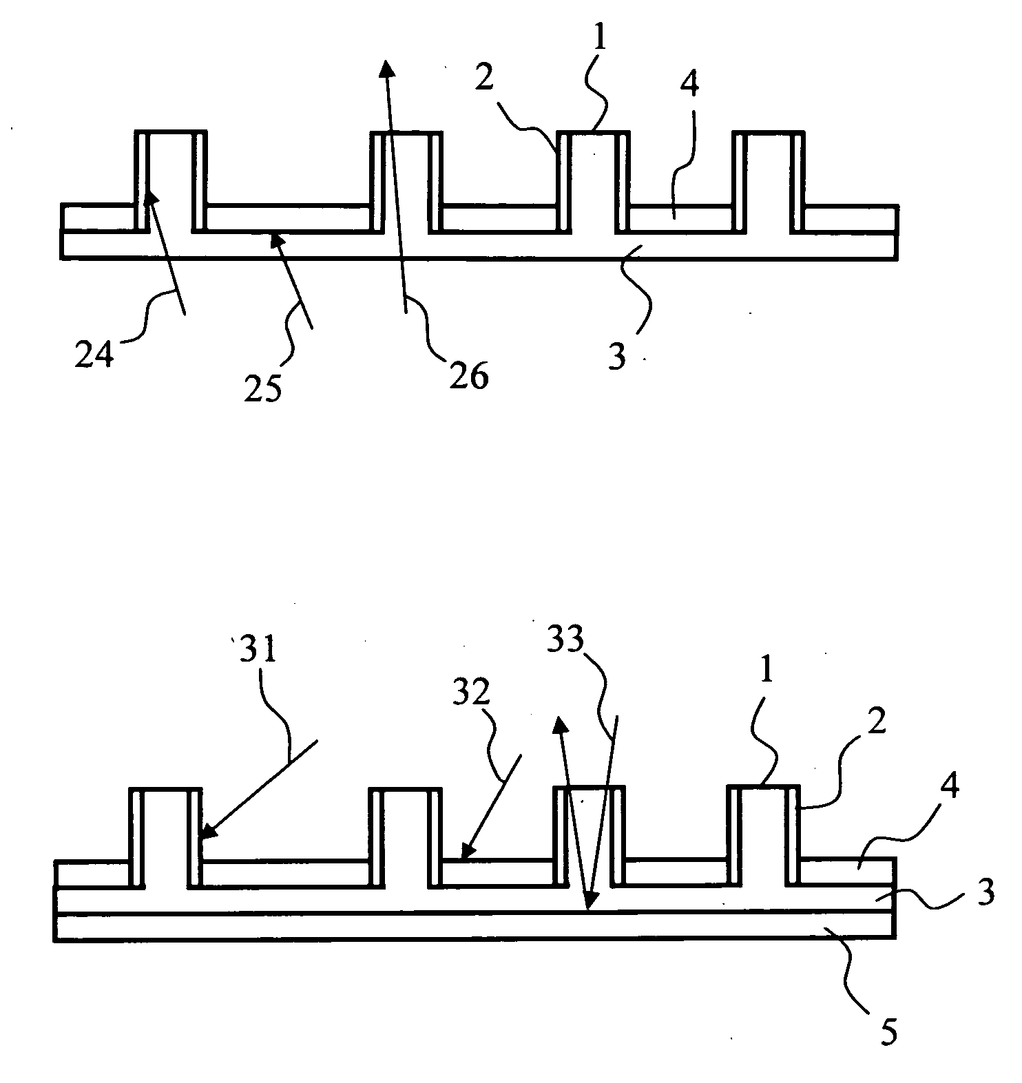
[0051] The behavior of light when a transparent material is used in the base material 3 of FIG. 1 will be described with reference to FIG. 2. FIG. 2 schematically shows the sectional structure of the screen of this example. Here, the case where the screen of this example is used as a ...

example 2

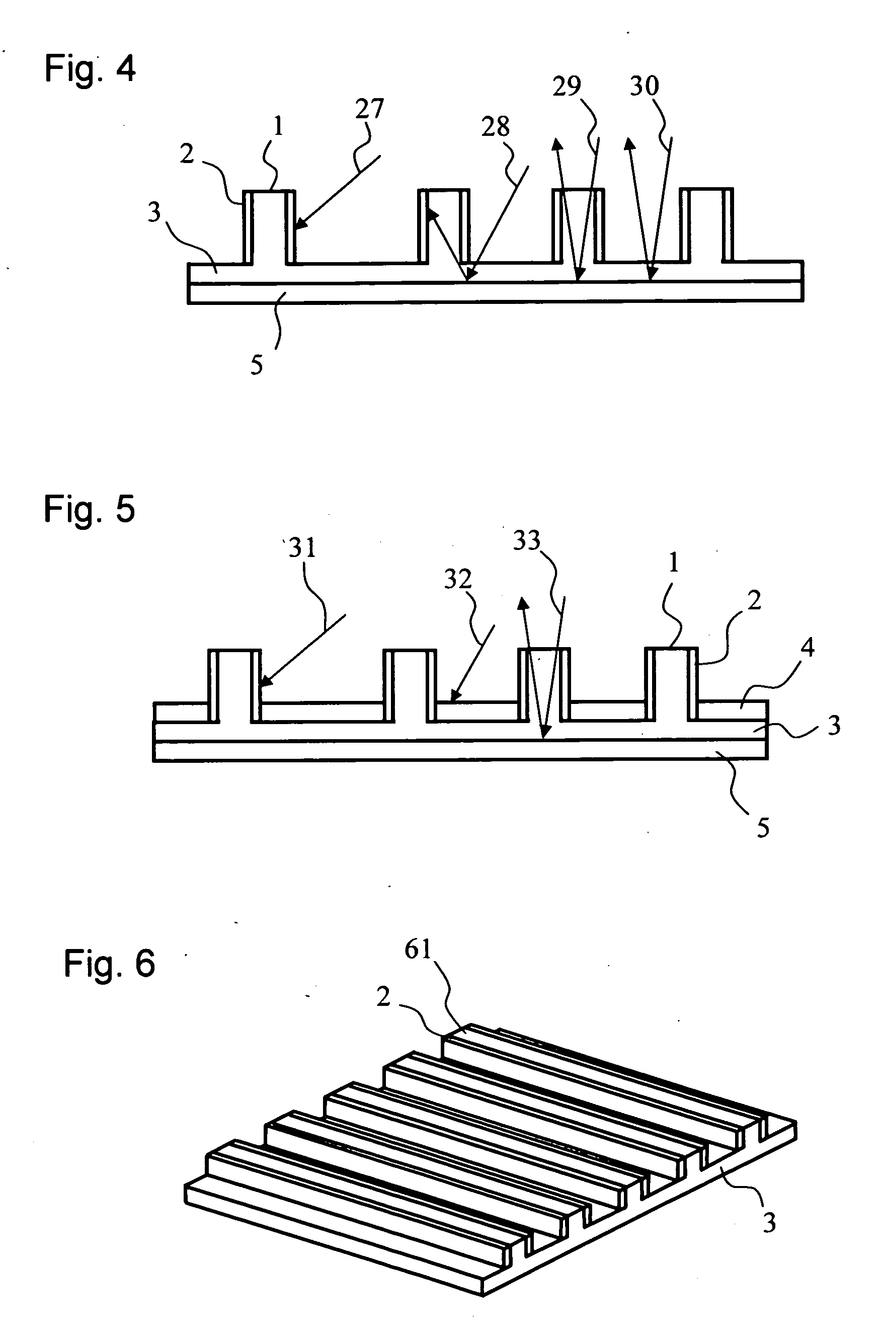
[0054]FIG. 4 schematically shows the sectional structure of a screen of this example. In this example, the screen is constituted to be a reflection type screen, that is, a front screen. In this example, after the multiple protrusions 1 have been formed on the base material 3 as in the case of FIG. 2, a light reflective layer 5 is formed on the surface of the base material 3 on which the protrusions 1 are not formed, that is, the rear surface of the base material. With such constitution, projection light 29 or 30 having a certain projection angle range transmits through the inside of each protrusion 1 or of the base material 3, and is then reflected on the light reflective layer 5 to enter the field of view of an observer. On the other hand, light except projection light from a projector has an angle of incidence larger than that of the projection light, and is obliquely incident on the screen like, for example, a light beam 27 or 28. In such case, nearly no light reaches an observer...

example 3

[0058]FIG. 6 schematically shows the external appearance of a screen of this example. In this example, linear protrusion structures 61 are formed in parallel with each other on the base material 3. In addition, the light absorbing layer 2 is formed on the side surface of each of the linear protrusion structures 61. That is, this example is different from Example 1 or Example 2 in the shape of a protrusion structure.

[0059] Light incident in parallel with each linear protrusion structure 61 except light directly incident on the light absorbing layer 2 behaves similarly to light incident on an ordinary transparent substrate, reflective substrate, or absorbable substrate, and it seems that the linear protrusion structures 61 are not formed on the surface. On the other hand, light incident even at a slight angle with respect to the direction parallel to each linear protrusion structure 61 behaves similarly to the light described with reference to FIG. 2, and the screen functions as a di...


PUM


Abstract

To provide a directional screen which can efficiently converge light from a projector on an observer and which is hardly affected by external light. That is, multiple transparent protrusion structures are formed on a base material, and a light absorbing layer communicating in the vertical direction of each of the protrusion structures is provided. The formation of a recess structure or a through-hole exerts an effect similar to that of a protrusion structure. Alternatively, fibrous protrusions each having a high light reflectance are used as the protrusion structures, and are densely formed on the base material while they -are slanted in the direction of external light.

Description

BACKGROUND OF THE INVENTION [0001] 1. Field of the Invention [0002] The present invention relates to a directional screen that displays an optical image projected from a projector such as a liquid crystal projector and an image projection system that displays an image by using the screen. [0003] 2. Description of the Related Art [0004] An image projection system such as a projection device that projects an optical image by using a high-intensity CRT, a liquid crystal projector, or the like to display an image has been widely used as a tool for communicating information to multiple users because the system can simply display a high-definition image on a large screen. There have been proposed ideas for the screen for a projector such as an improvement in efficiency for light utilization through the coverage of the surface of the screen with a white material or light reflective film having a high light reflectance and an improvement in visibility for multiple observers through light di...

Claims


Application Information

Patent Timeline
IPC IPC(8): G03B21/56
CPCG03B21/60G03B21/56
Inventor YAMAUCHI, NAOFUMI
Owner YAMAUCHI NAOFUMI
Why Eureka
Try Eureka