Audio image control device and design tool and audio image control device

a control device and audio image technology, applied in the direction of stereophonic communication headphones, stereo-stereo systems, stereophonic arrangments, etc., can solve the problems of difficult stabilization of measurement conditions, difficult control of sound images correctly, and measurement of an enormous number of transfer functions, so as to achieve precise localization of sound images, accurate obtain enormous kinds of transfer functions, and high speed

Active Publication Date: 2006-12-07
PANASONIC CORP
View PDF12 Cites 52 Cited by
  • Summary
  • Abstract
  • Description
  • Claims
  • Application Information

AI Technical Summary

Benefits of technology

[0016] According to the present invention, precise localization of sound images is achieved even when acoustic transducers located close to the head are used since it is possible to accurately obtain enormous kinds of transfer functions for different azimuthal angles, elevation angles, and distances between a sound source and a head model under the same condition at high speed and to obtain highly precise transfer functions even when the acoustic transducers are located close to the head. What is more, it is possible to support individual differences in sound interference that varies depending on head dimensions as well as differences in the internal shape of ear canals and thus to reduce individual differences in the effect of sound image control.

Problems solved by technology

However, such conventional structure requires the measurement of an enormous number of transfer functions in the case of measuring detailed variations in azimuthal and elevation angles.
With regard to this, there are following problems: (1) it is difficult to stabilize a measurement condition each time the location of the speaker is changed; (2) the size of microphones used for measurement cannot be ignored while the size of ear canals is ignorable; and (3) due to such reasons as that the size of the speaker has an affect on the sound field in the case where HRTFs are measured in the vicinity of the head, highly accurate HRTFs cannot be obtained, and thus in the case where an acoustic transducer located in the vicinity of one meter or less away from the head is used, it is difficult to control sound images correctly.
Furthermore, also in the case where HRTFs are determined on a calculator, while it is desired to calculate HRTFs with the sound source being placed in a larger number of different locations, there is a problem that it requires the calculation of the potential of each of an enormous number of nodal points each time the location of the sound source is changed.
There is also a problem that, since modification of transfer functions according to head dimensions is made by adjusting an inter-ear delay time in the case where the head is regarded simply as a sphere, variations in the frequency characteristics attributable to an interference between sounds that diffract around the head cannot be reproduced and thus differences in the effect of sound image control among individuals cannot be reduced.

Method used


Image

  • Audio image control device and design tool and audio image control device
  • Audio image control device and design tool and audio image control device
  • Audio image control device and design tool and audio image control device

Examples


first embodiment

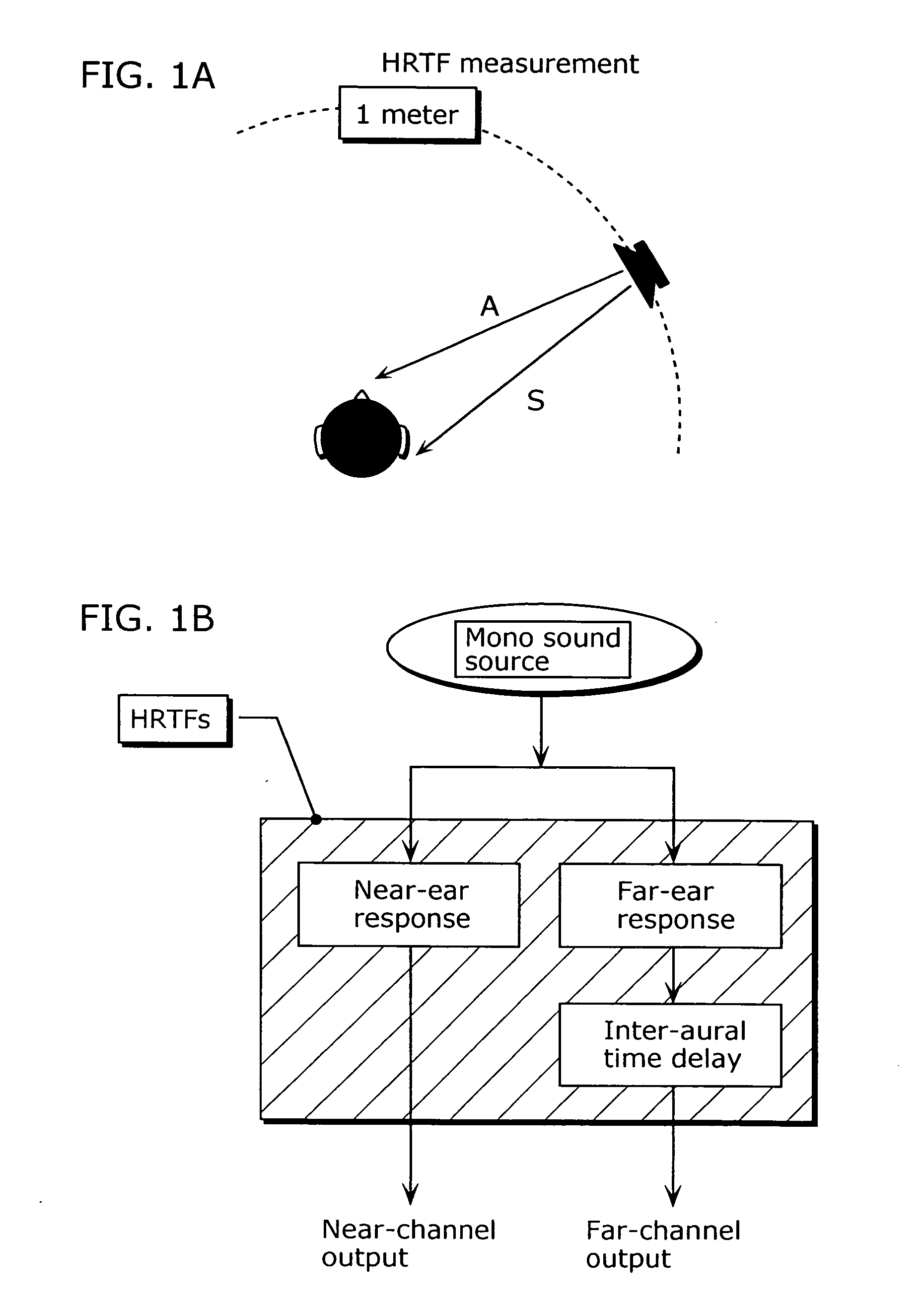
[0057] A sound image control device according to the first embodiment of the present invention obtains precise localization of sound images by determining transfer functions by use of a three-dimensional head model that has a human body shape and is represented on a calculator, according to a calculation model in which the positions of sound sources and sound receiving points are reversed, by means of numerical calculations employing the boundary element method, and then by controlling sound images using such transfer functions.

[0058] Details about the boundary element method are introduced, for example, in “Masataka TANAKA, et. al, “kyoukai youso hou (Boundary Element Method)”, pp. 40-42 and pp. 111-128, 1991, Baifukan Inc.) (hereinafter referred to as “Non-patent document 1”).

[0059] Using this boundary element method, it is possible to perform such a calculation as is described in “Papers of 2001 Autumn Meeting of Acoustical Society of Japan (pp. 403-404)) (hereinafter referred ...

second embodiment

[0074] The second embodiment describes the case where the sound image control device of the first embodiment is applied to sound listening using a headphone so as to obtain precise localization of sound images also in the case of sound listening using a headphone.

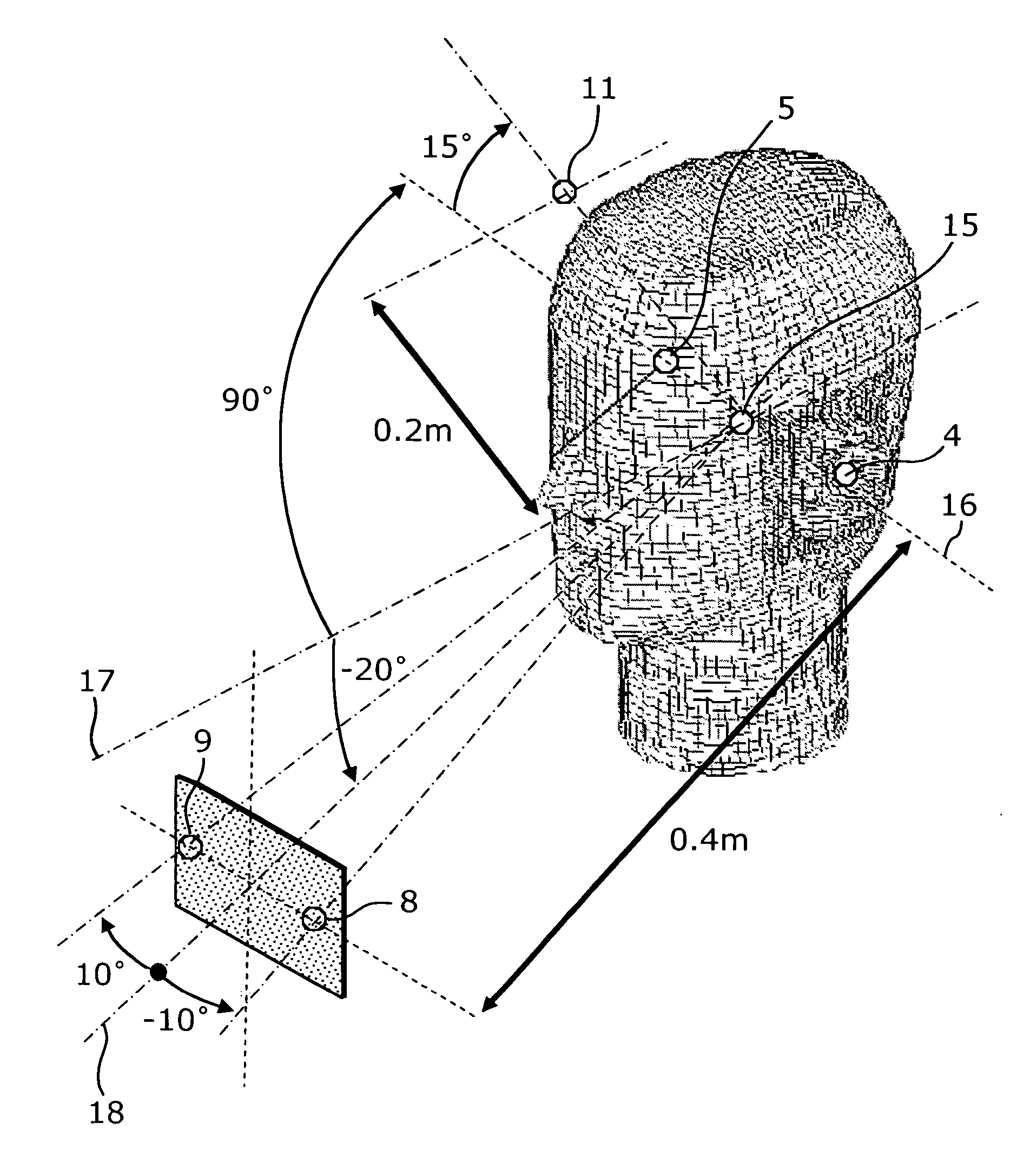
[0075]FIG. 11 is a diagram showing a calculation model for calculating transfer functions from acoustic transducers of a sound image control device of the second embodiment to the entrances to the respective ear canals. In FIG. 11, the same constituent elements as those shown in FIG. 6 are assigned the same reference numbers, and descriptions thereof are not provided. FIG. 11 illustrates a calculation model corresponding to the one for a so-called headphone listening in which the acoustic transducer 8 and the acoustic transducer 9 are placed close to the respective ears of the head model 3. In other words, the sound emitting point 4 located at the left ear canal allows the sound pressure generated at the sound receiving po...

third embodiment

[0079] The first and second embodiments describe the case where sound emitting points are placed at the entrances to the respective ear canals, but the third embodiment describes the case where more precise localization of sound images is achieved by placing sound emitting points at the respective eardrums so as to determine transfer functions to a target sound source.

[0080]FIG. 13 is a diagram showing a more detailed 3-D shape of the right pinna region of the head model 3. FIG. 13A is a front view showing the right pinna region of the head model 3, and FIG. 13B is a top view showing the right pinna region of the head model 3. As shown in these drawings, an eardrum 23 is formed on the ear canal 21 starting from the ear canal entrance 1. The third embodiment is the same as the first embodiment except that the ends of the respective ear canals of the head model 3 are closed by the eardrums.

[0081]FIG. 14 is a diagram showing an example calculation model for calculating transfer funct...


PUM


Abstract

The sound image control device filters transfer functions H3 and H1 indicating transfer characteristics of a sound from an acoustic transducer (8) to entrances to respective ear canals (1) and (2) as well as filtering transfer functions H4 and H2 from an acoustic transducer (9) to the entrances to the respective ear canals (1) and (2) and generates second transfer functions H6 and H5 indicating transfer characteristics of a sound to the entrances to the respective ear canals (1) and (2) from a target sound source (11) at a location different from the sound sources, the sound image control device being equipped with correction filters (13) and (14) that (i) store characteristic functions E1 and E2 for performing filtering operations on the first transfer functions H1, H2, H3, and H4 and (ii) generate the second transfer functions H5 and H6 from the first transfer functions H1, H2, H3, and H4 using such characteristic functions E1 and E2.

Description

TECHNICAL FIELD [0001] The present invention relates to a sound image control device that localizes, using a sound transducer such as a speaker and a headphone, a sound image at a position other than where such sound transducer exists, and relates to a design tool for designing a sound image control device. BACKGROUND ART [0002] Conventionally, a method has been known for representing the sound transmitted from a speaker to the ears using head-related transfer functions (HRTF(s)). HRTFs are functions that represent how the sound being generated from the speaker (sound source) sounds to the ears. By applying filtering on the sound source such as a speaker using such HRTFs, it is possible to give a person a feeling that there is a sound source in a location where such sound source does not actually exist. This processing is referred to as “localizing a sound image” at the location. The HRTFs can be determined either by actual measurement or by calculations. The successful application ...

Claims


Application Information

Patent Timeline
Patent Type & Authority Applications(United States)
IPC IPC(8): H04R5/00H04R5/027H04R5/033H04S1/00H04S5/02H04S7/00
CPCH04S2420/01H04S1/005H04R5/00H04S5/00H04S5/02H04S7/00
Inventor TERAI, KENICHIABE, KAZUTAKAKAKUHARI, ISAOWATANABE, YASUHITOITO, GEMPO
Owner PANASONIC CORP
Why Eureka
Try Eureka