Method for generating jolting table shock response

A technology of shock response and vibration table, applied in the field of vibration table shock response generation, can solve problems such as unfavorable engineering application, cumbersome operation, cumbersome process, etc., and achieve the effect of high reliability, less system resources and consistent response

Inactive Publication Date: 2011-11-09
HARBIN INST OF TECH
View PDF0 Cites 0 Cited by
  • Summary
  • Abstract
  • Description
  • Claims
  • Application Information

AI Technical Summary

Problems solved by technology

This type of method realizes the shock response by real-time testing and modifying the control signal. On the one hand, the process of this type of method is cumbersome and requires Fourier transform, closed-loop control, etc., and the hardware requirements of the entire control system are increased; on the other hand, During the correction of the shock test, some parameters of the simulated shock waveform, such as amplitude and time delay, will be affected by factors such as noise and equipment, and will change. Although the shock waveform meets the expected requirements, it cannot be guaranteed that the shock will be generated during the shock test. When , the driving signal is the same each time, which will introduce unquantifiable disturbances to the experimental results
[0005] To achieve a good control of the shaking table, it is very important to obtain its transfer function. However, there are few researches on the identification of shaking table parameters. There are only some research methods based on the measurement of frequency characteristics to estimate parameters, and the operation is cumbersome, which is not conducive to engineering applications.

Method used


Image

  • Method for generating jolting table shock response
  • Method for generating jolting table shock response
  • Method for generating jolting table shock response

Examples


Embodiment 1

[0030] Example 1: Combining figure 1 , figure 2 , the present invention is a vibration table shock response generation method, the steps of the shock response generation method are as follows:

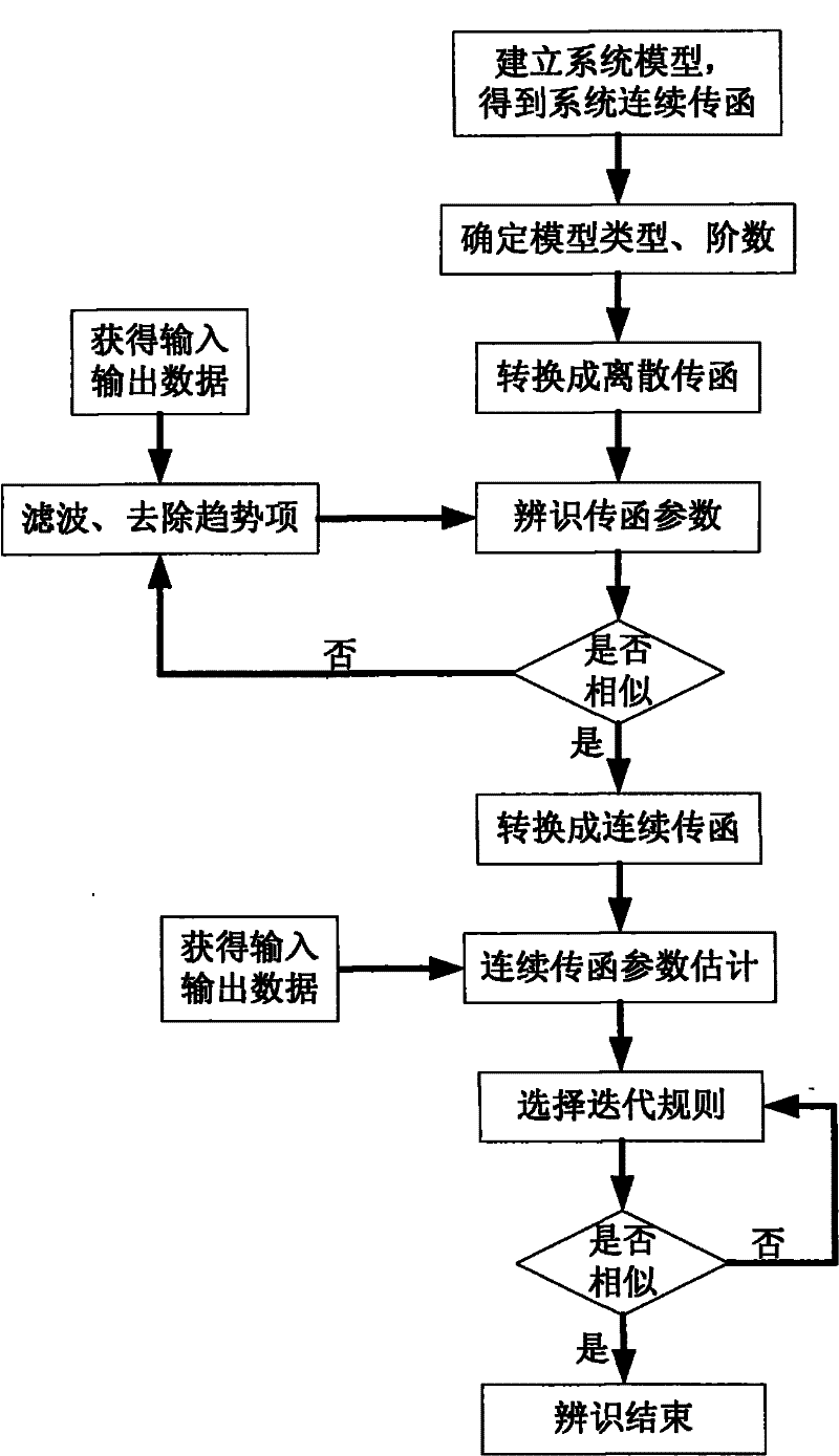
[0031] 1. Analyze the mechanical model of the shaking table to obtain its theoretical transfer function; deduce its discrete transfer function according to the theoretical transfer function, and then determine the number of zero poles;

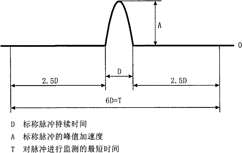
[0032] 2. According to the identification waveform diagram ( figure 1 ) is used as the input signal of the vibration table, which is loaded to the vibration table through the vibration table control drive system;

[0033] 3. The acceleration signal is output from the acceleration sensor on the vibrating table to an oscilloscope that can store waveforms, and the oscilloscope simultaneously records the input signal of the vibrating table;

[0034] 4. Save the input and output data of the previous step to the host computer, and use the signal processi...

Embodiment 2

[0043] Example 2, combined with figure 1 , figure 2 , image 3 , Figure 4 , Figure 5 , the vibration table shock response generation method of the present invention, the specific implementation steps are as follows:

[0044] The vibrating table chosen to generate shock is a domestic small electric vibrating table.

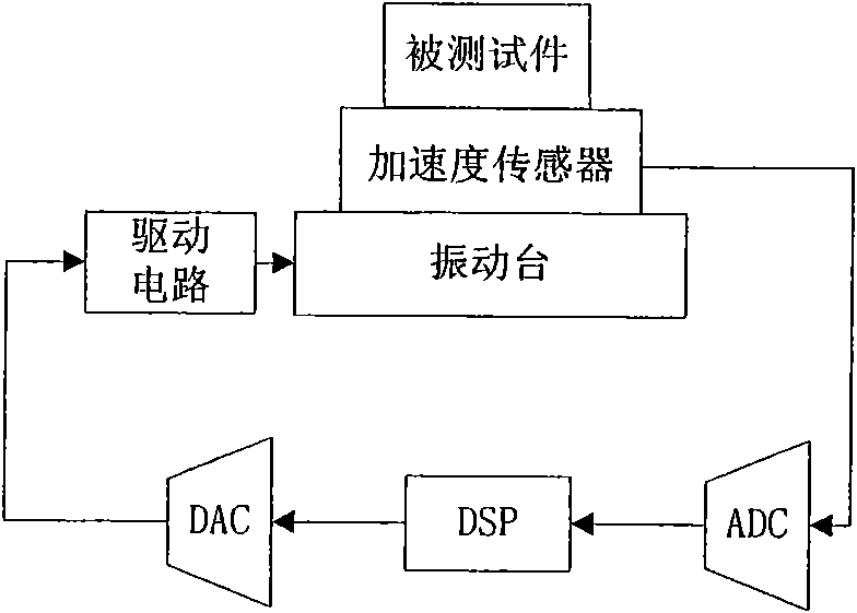
[0045] The first step is to analyze the mechanical model of the shaking table to obtain its theoretical transfer function; deduce its discrete transfer function according to the theoretical transfer function, and then determine the number of zero poles; (combined with image 3 )

[0046]

[0047]

[0048]

[0049]

[0050] where u F —Input voltage; L o —Equivalent inductance of filter; C o —Equivalent capacitance of the filter; R L —Equivalent resistance of filter; i L —coil current; u o—coil voltage; R—equivalent resistance; L—equivalent inductance; B—air gap magnetic density; F—electromotive force; m—mass of armature and table; c—damping...


PUM


Abstract

The invention aims at providing a method for generating jolting table shock response which is characterized by low system resource utilization, consistent response under each shock and high reliability. The method comprises the steps: a mechanical model of the jolting table is analyzed to obtain a theoretic transfer function of the jolting table; the form shown in a waveform is identified as an input signal of the jolting table and the signal is loaded to the jolting table by a control and drive system of the jolting table; system identification is conducted and PID stimulation calculation isconducted in a simulink according to the obtained transfer function until a shock response conforms to the wave reproducibility method specified by the GJB standards is generated; the stimulation result is applied to the reality and meets the requirements by open-loop control; the PID parameter can also be used to closed-loop control to generate a shock response conforming to the GJB standards. The shock response generated by the method strictly meets the GJB standards and is characterized by low system resource utilization and consistent response under each shock and high reliability.

Description

(1) Technical field [0001] The invention relates to a vibration table control technology, in particular to a vibration table shock response generation method. (2) Background technology [0002] In order to ensure the adaptability of products to withstand non-repetitive mechanical shocks, many products need to undergo shock tests before leaving the factory, especially military equipment. The purpose of the impact test is mainly to determine the adaptability of components and equipment to withstand non-repeated mechanical shocks during use and transportation, and to evaluate the integrity of the structure. Secondly, it can also be used for internal strength tests of microelectronic devices. Switching devices such as relays are more susceptible to shocks. The national military standard 65B has detailed regulations on relays. When the relay is tested according to the conditions A, B or C specified in the method 213 of the national military standard 360A, the opening of the close...

Claims


Application Information

Patent Timeline
Patent Type & Authority Patents(China)
IPC IPC(8): G01M7/02G01M7/08
Inventor 翟国富康云志任万滨梁慧敏王健
Owner HARBIN INST OF TECH
Why Eureka
Try Eureka