Electric signal line connector

Inactive Publication Date: 2006-12-07
CHEN CHIUNG LING +1
View PDF4 Cites 63 Cited by
  • Summary
  • Abstract
  • Description
  • Claims
  • Application Information

AI Technical Summary

Benefits of technology

[0012] The present invention has been accomplished under the circumstances in view. It is one object of the present invention to provide an electric signal line connector, which firmly

Problems solved by technology

When crimping the thin tube, the tin tube may break along the seam thereof, and the signal line may easily be forced out of place or disconnected from the electric signal line connector.
Because the mold is formed of a number of mold blocks, the mold cost is relatively high, and the fabrication of the mold is relatively complicated.
In consequence, the m

Method used


Image

  • Electric signal line connector
  • Electric signal line connector
  • Electric signal line connector

Examples


Embodiment Construction

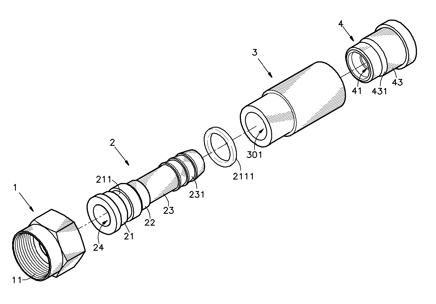
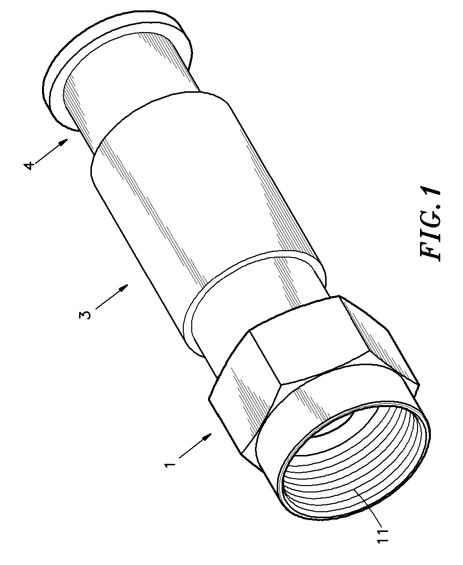
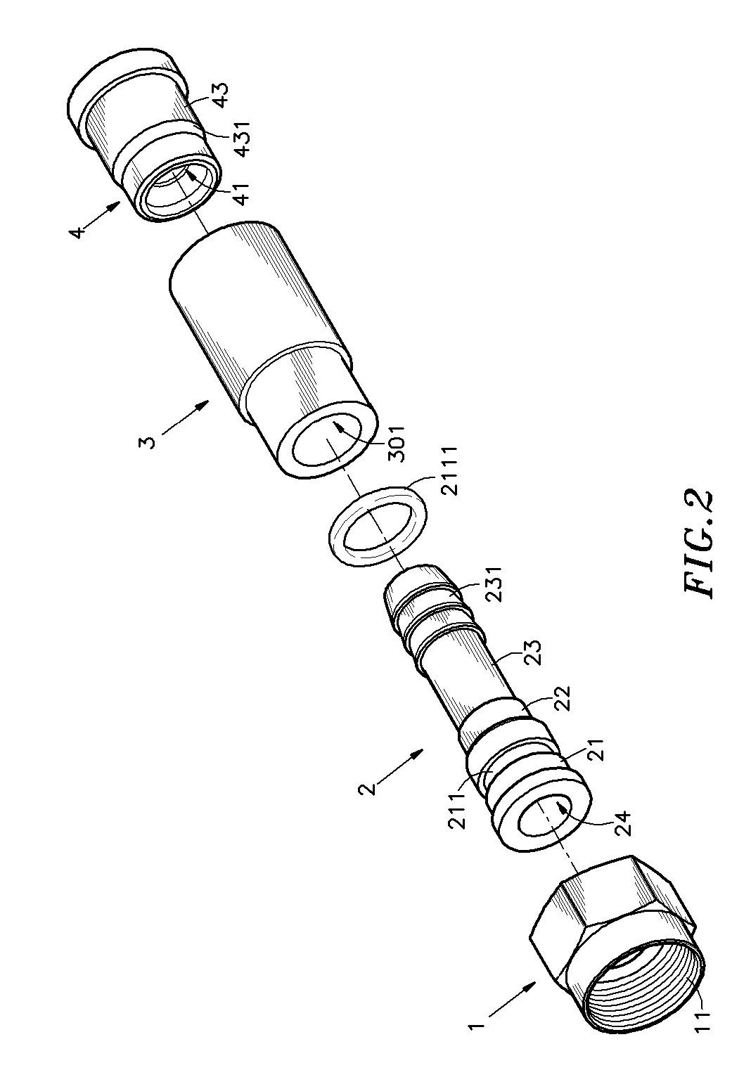
[0022] Referring to FIGS. 1˜3, an electric signal line connector in accordance with the present invention is shown comprising a locknut 1, a holding-down tube 2, a tubular shell 3, and a socket 4.

[0023] The locknut 1 has an inner thread 11 at one end, and an stop flange 12 at the other end.

[0024] The holding-down tube 2 comprises a tubular bearing portion 21, a locating groove 211 extending around the periphery of the tubular bearing portion 21, a tubular extension 23 axially extending from one end of the tubular bearing portion 21, a tubular coupling portion 22 axially connected between the tubular bearing portion 21 and the tubular extension 23, an axial center through hole 24 surrounded by the tubular bearing portion 21 and the tubular coupling portion 22 and the tubular extension 23, and a plurality of barbed portions 231 extending around the distal end of the tubular extension 23 remote from the tubular bearing portion 21 and the tubular coupling portion 22. Further, a gasket...


PUM


Abstract

An electric signal connector for fastening to a coaxial cable type signal line is disclosed formed of a locknut, a holding-down tube, a tubular shell and a socket. The tubular shell has a retaining inside wall with an inner diameter made gradually reducing toward inside of the tubular shell for receiving the socket and an inside annular step for stopping against the socket. The socket is stopped against the inside annular step of the tubular shell, having a outside positioning wall peripherally stopped against the retaining inside wall of the tubular shell, and an inside bearing annular step for stopping a tube of conducting material of the coaxial cable type signal line against the barbed portions.

Description

[0001] This application claims the priority benefit of Taiwan patent application number 094209421 filed on Jun. 6, 2005. BACKGROUND OF THE INVENTION [0002] 1. Field of the Invention [0003] The present invention relates to electric connectors and more particularly, to an electric signal line connector, which firmly secures the signal line against twist, enabling the signal line to transmit signal smoothly without noises. [0004] 2. Description of the Related Art [0005] An early electric signal line connector is known comprising a connector body, and a thin tube coupled to one end of the connector body. After insertion of the signal line into the thin tube and the connector body, a crimping tool is used to crimp the thin tube, fastening the thin tube to the signal line. When crimping the thin tube, the tin tube may break along the seam thereof, and the signal line may easily be forced out of place or disconnected from the electric signal line connector. [0006]FIGS. 7 and 8 show a prior...

Claims


Application Information

Patent Timeline
IPC IPC(8): H01R9/05H01R13/504H01R13/52H01R13/622H01R13/646H01R24/02
CPCH01R9/0524H01R13/5045H01R2103/00H01R13/622H01R24/40H01R13/5202
Inventor CHEN, CHIUNG-LING
Owner CHEN CHIUNG LING
Why Eureka
Try Eureka