
Dynamic Ankle Orthesis

a dynamic ankle and orthesis technology, applied in the field of dynamic ankle orthesis, can solve the problems of insufficient positioning control, deterioration of proprioceptive function, spasms and unbalance of patients, etc., and achieve the effect of improving the dynamic ankle orthesis

Inactive Publication Date: 2006-12-07
ORTEC INC
View PDF8 Cites 15 Cited by
  • Summary
  • Abstract
  • Description
  • Claims
  • Application Information

AI Technical Summary

Benefits of technology

[0013] It is an object of the present invention to provide an improved dynamic ankle orthesis, to be worn on a foot.
[0025] According to embodiments of the present invention, the height of front and the rear bearing surfaces of the pivot could be different or similar which makes it possible to support differently the extension or the inflection of the foot or to have an equal effect.

Problems solved by technology

Some patients suffer from pathology like multiple sclerosis, hemiplegics, myopathy or traumatic repercussions, generating neuromuscular problems, causing an insufficient control of positioning, and maintaining of its position, of the foot and the leg during walking.
Immobilization of the joint results in deterioration of proprioceptive function.
In addition, this loss of perception, combined with a stringent positioning of the foot wearing the orthesis, may cause spasms and unbalancing of the patient.

Method used


Image

  • Dynamic Ankle Orthesis
  • Dynamic Ankle Orthesis
  • Dynamic Ankle Orthesis

Examples


Embodiment Construction

[0036] The present invention will be described with respect to particular embodiments and with reference to certain drawings but the invention is not limited thereto but only by the claims. The drawings described are only schematic and are non-limiting. In the drawings, the size of some of the elements may be exaggerated and not drawn on scale for illustrative purposes. The dimensions and the relative dimensions do not correspond to actual reductions to practice of the invention.

[0037] Furthermore, the terms first, second, third and the like in the description and in the claims, are used for distinguishing between similar elements and not necessarily for describing a sequential or chronological order. It is to be understood that the terms so used are interchangeable under appropriate circumstances and that the embodiments of the invention described herein are capable of operation in other sequences than described or illustrated herein.

[0038] Moreover, the terms top, bottom, over, ...


PUM


Abstract

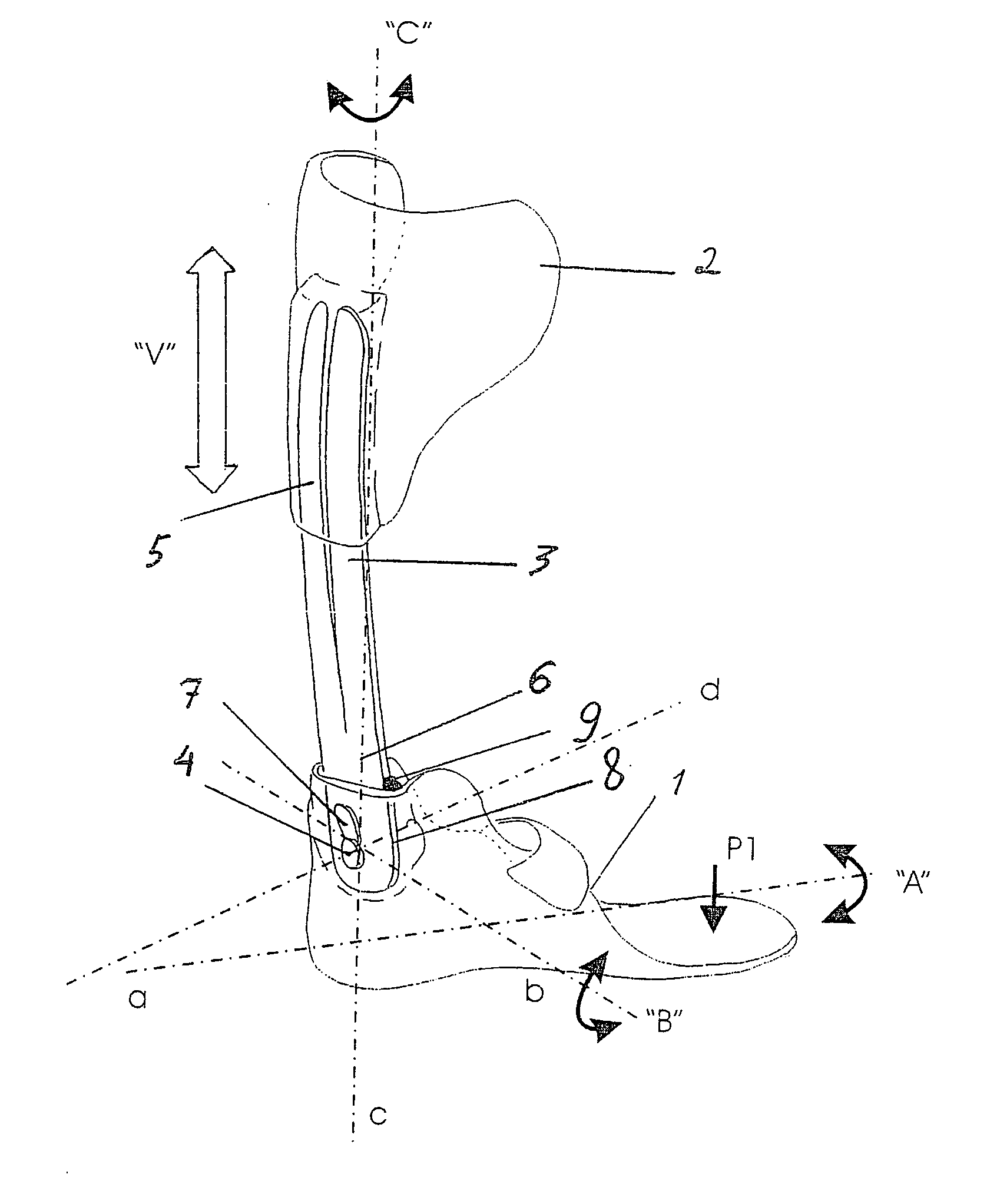
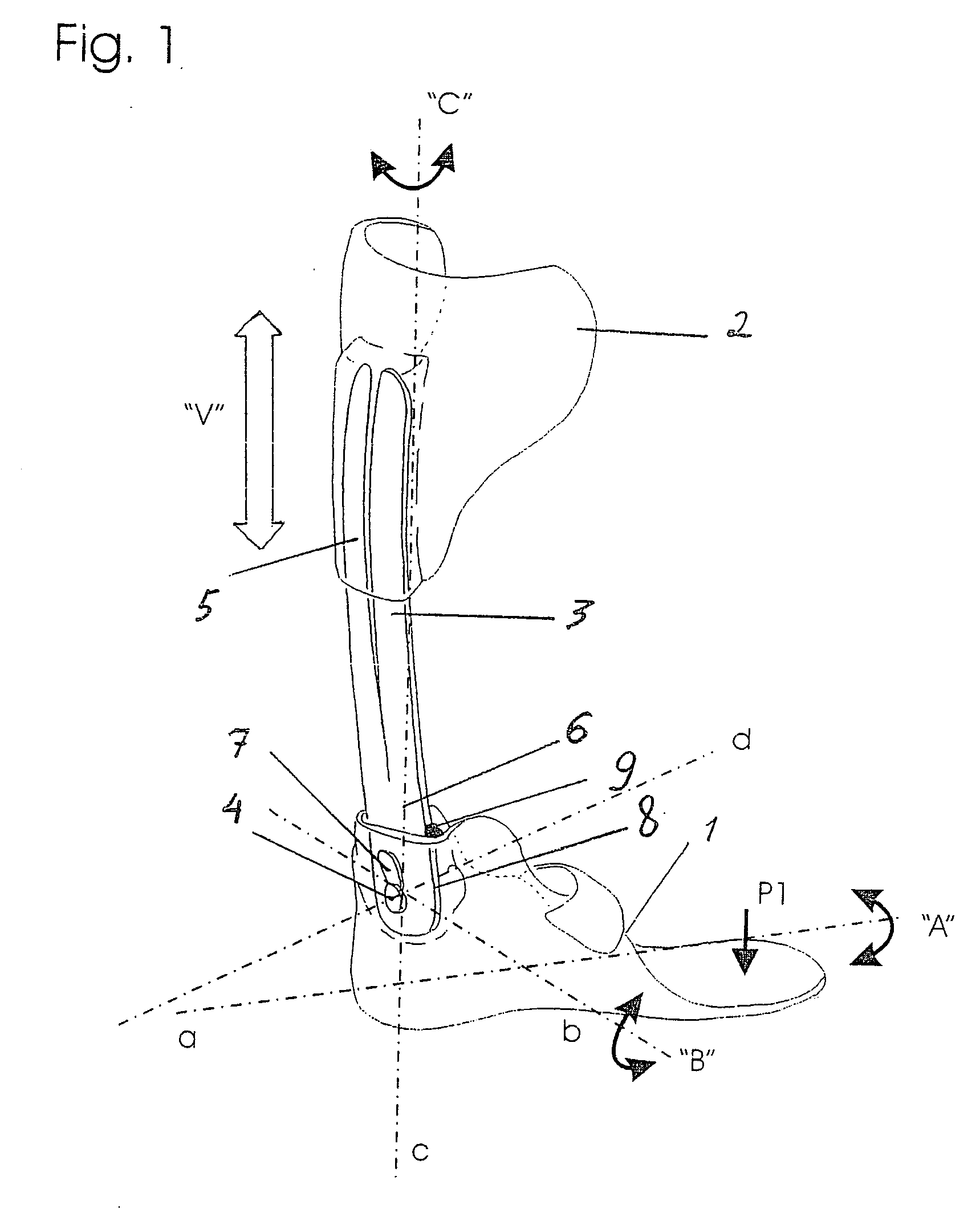
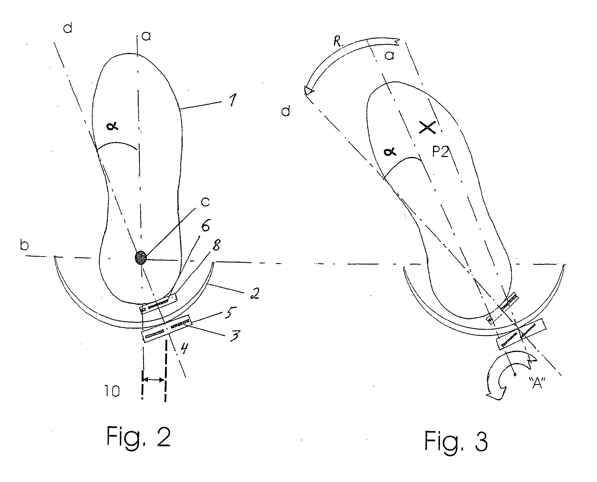
A dynamic ankle orthesis as subject of the present invention comprises a shoe insert (1) having a heel, a cuff (2) and a springy means (3, 6) for coupling the shoe insert (1) and the cuff (2). The springy means is coupled at its lower part (6) to the shoe insert (1) by means of a pivot (4) located at the heel of the shoe insert (1). The orthesis according to the present invention allows control and assistance of the foot during rotation around each of the three axes of rotation of the foot and heel in a distinct way during each of the phases of a step.

Description

TECHNICAL FIELD OF THE INVENTION [0001] The present invention relates to a dynamic ankle orthesis, especially an orthesis for maintaining the dynamical behaviour of the combination of foot-ankle-leg, and for assisting and / or correcting neuromuscular deficiencies related to the three rotation axes of the foot. Rotations corresponding to these three rotation axes are a rotation around the vertical axis of the leg, stretching and bending of the ankle around the axis of the ankle and supination / pronation, this is rotation around the longitudinal axis of the foot. BACKGROUND OF THE INVENTION [0002] A normal step of a person comprises several consecutive phases. In a first phase, called “heel-strike phase”, the heel is placed on the ground under a slight supination, this is the foot being slightly inclined to the exterior side of the foot. The contact of the foot with the ground is made at the external back part of the heel. [0003] In a second phase, called “mid-stance phase”, the sole of...

Claims


Application Information

Patent Timeline
Patent Type & Authority Applications(United States)
IPC IPC(8): A61F5/00A61F5/37
CPCA61F2005/0179A61F5/0127
Inventor DEVREESE, SERGE LUCIEN PIERRE MICHEL
Owner ORTEC INC
Learn More