Inter-cervical facet implant distraction tool

a facet implant and tool technology, applied in the field of facet implants and tools, can solve the problems of reducing the foraminal area, radicular pain, neck pain and muscle weakness,

Inactive Publication Date: 2006-12-07
KYPHON
View PDF99 Cites 140 Cited by
  • Summary
  • Abstract
  • Description
  • Claims
  • Application Information

AI Technical Summary

Problems solved by technology

Spinal stenosis results in a reduction foraminal area (i.e., the available space for the passage of nerves and blood vessels) which compresses the cervical nerve roots and causes radicular pain.
Another symptom of spinal stenosis is myelopathy, which results in neck pain and muscle weakness.
Extension and ipsilateral rotation of the neck further reduces the foraminal area and contributes to pain, nerve root compression, and neural injury.

Method used


Image

  • Inter-cervical facet implant distraction tool
  • Inter-cervical facet implant distraction tool
  • Inter-cervical facet implant distraction tool

Examples


Embodiment Construction

[0029] Embodiments of the present invention provide a tool for implanting a minimally invasive surgical apparatus that preserves the physiology of the spine. In particular, the tool preferably distracts the facets in the cervical spine to allow insertion of the implant, whereby the implant increases the foramina dimension in extension and neutral positions. Such implants distract, or increase the space between, the vertebrae to increase the foraminal area or dimension, and reduce pressure on the nerves and blood vessels of the cervical spine. In a specific preferred embodiment, an implanted inter-facet spacer of 1.5 mm to 2.5 mm in width can result in inter-facet distraction that increases foramina dimension in extension and neutral. Other inter-facet spacer dimensions also are contemplated by the invention described herein below.

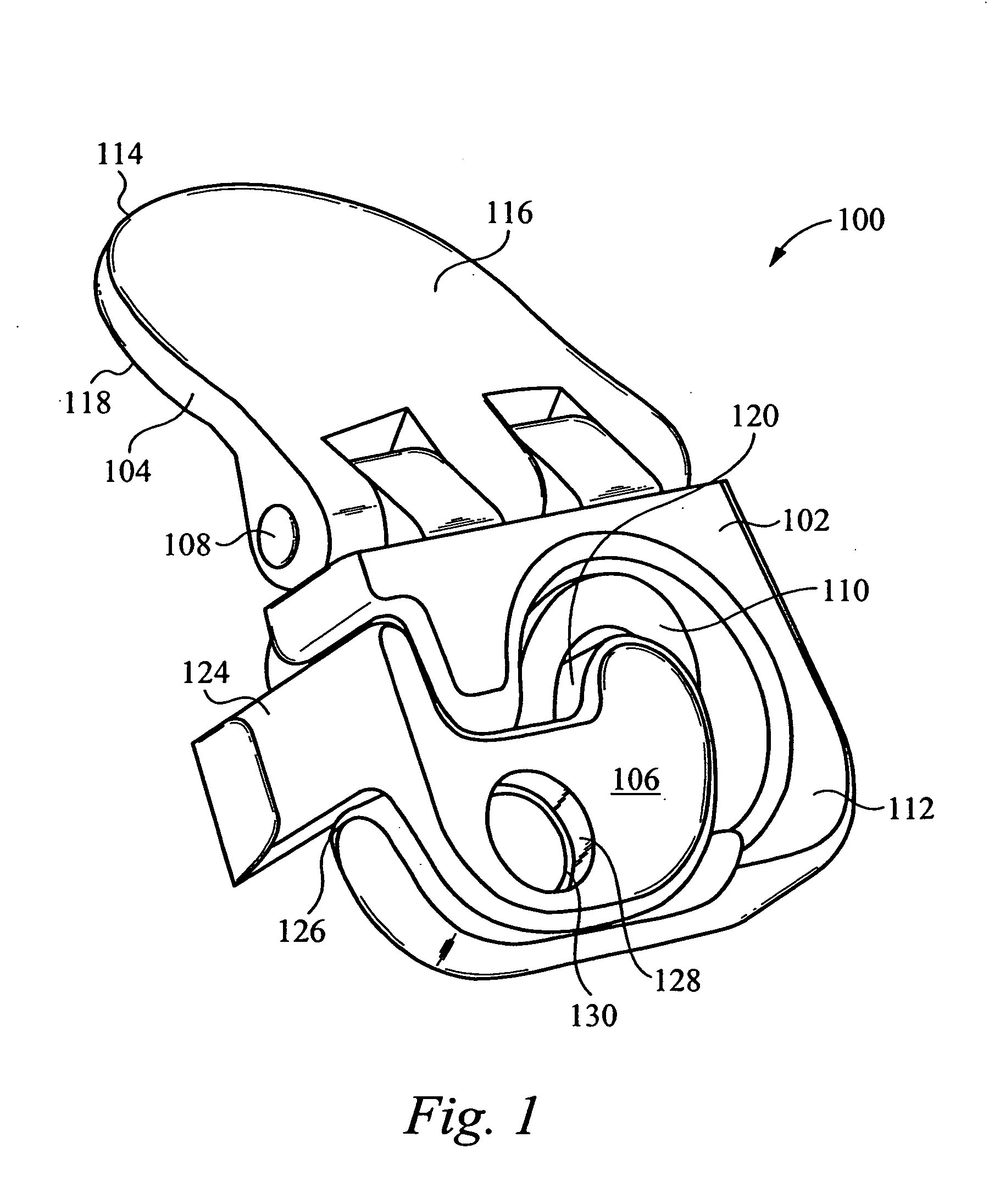
[0030]FIG. 1 illustrates a perspective view of an inter-facet cervical implant 100 in accordance with the present invention. In the embodiment depicted in...


PUM


Abstract

A distraction tool is disclosed which distracts, and preferably sizes, adjoining facets of a spine for an implant. The tool preferably includes a distraction head that has a first and a second head component. The first head component and the second head component preferably include inter-digitated fingers when the distraction head is in a non-distracted position. The tool includes a handle which is actuatable to move the distraction head to a distracted position, whereby the first set and second set of fingers are separated from one another. The tool can include a distraction gauge as well as a locking mechanism. The tool can also include a movement limitation mechanism to control the amount of distraction which the tool undergoes when actuated. The tool can include an insertion feature to allow the implant to be inserted into the facet joint while the tool is distracting the facets apart.

Description

PRIORITY CLAIM [0001] This application claims priority to U.S. Provisional Patent Application No. 60 / 668,053, filed Apr. 4, 2005, entitled “INTER-CERVICAL FACET IMPLANT DISTRACTION TOOL” (KLYC-01095US2).RELATED APPLICATIONS [0002] This patent application is related to the following applications, all of which are hereby incorporated herein by reference: [0003] U.S. Application No. 60 / 635,453, entitled “INTER-CERVICAL FACET IMPLANT AND METHOD”, filed Dec. 13, 2004 [Atty. Docket No. KLYC-01118US0]; [0004] U.S. application Ser. No. 11 / 053,399, entitled “INTER-CERVICAL FACET IMPLANT AND METHOD”, filed Feb. 8, 2005 [Atty. Docket No. KLYC-01118US1]; [0005] U.S. application Ser. No. 11 / 053,624, entitled “INTER-CERVICAL FACET IMPLANT AND METHOD”, filed Feb. 8, 2005 [Atty. Docket No. KLYC-01118US2]; [0006] U.S. application Ser. No. 11 / 053,735, entitled INTER-CERVICAL FACET IMPLANT AND METHOD, filed Feb. 8, 2005 [Atty. Docket No. KLYC-01118US3]; and [0007] U.S. application Ser. No. 11 / 053,346,...

Claims


Application Information

Patent Timeline
Patent Type & Authority Applications(United States)
IPC IPC(8): A61B17/58
CPCA61B17/025A61B2017/0256A61B2019/464A61B2019/461A61B2019/304A61B2090/034A61B2090/061A61B2090/064
Inventor YERBY, SCOTT A.MITCHELL, STEVEN T.WINSLOW, CHARLES J.
Owner KYPHON
Why Eureka
Try Eureka