Vacuum cleaner

a vacuum cleaner and vacuum technology, applied in the field of vacuum cleaners, can solve the problems of large flow resistance of the discharge passage, noise and vibration generated by the motor, and achieve the effect of preventing the noise of the blower uni

Inactive Publication Date: 2006-12-14
SAMSUNG ELECTRONICS CO LTD
View PDF9 Cites 49 Cited by
  • Summary
  • Abstract
  • Description
  • Claims
  • Application Information

AI Technical Summary

Benefits of technology

[0020] It is another aspect of the present invention to provide a vacuum cleaner including a main body forming an outer appearance of the vacuum cleaner and including a blower unit to generate a suction force and a blowing force and a discharge hole through which purified air from which f

Problems solved by technology

As such, since air flows due to the suction force and the blowing force during an operation of the motor and the blower fan, noise and vibration are generated from the motor and the blower fan of the blower unit.
However, in the conventional vacuum cleaner, since a length of a discharge passage for guiding air discharged from the blower unit to be discharged is short, noise generated by the b

Method used


Image

  • Vacuum cleaner
  • Vacuum cleaner
  • Vacuum cleaner

Examples


Embodiment Construction

[0025] Reference will now be made in detail to the embodiments of the present invention, examples of which are illustrated in the accompanying drawings, wherein like reference numerals refer to the like elements throughout. The embodiments are described below to explain the present invention by referring to the figures.

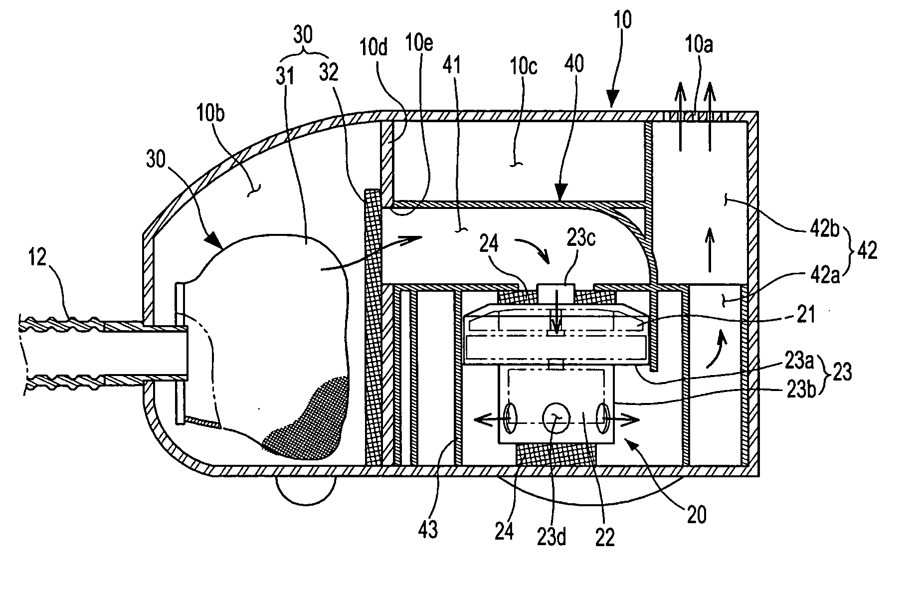
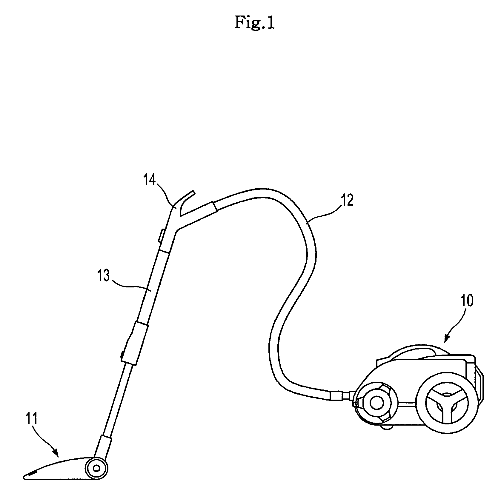
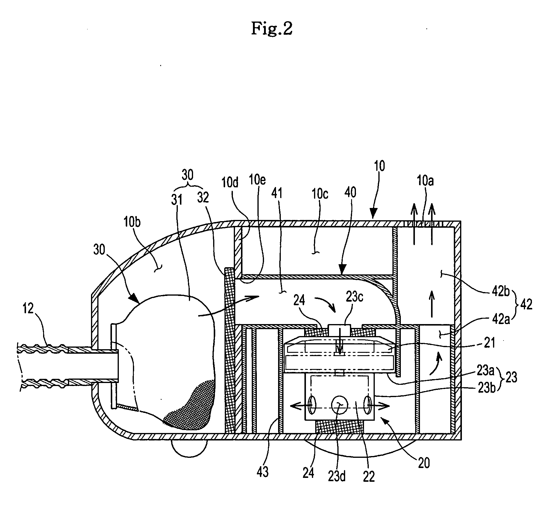
[0026] In FIG. 1, the vacuum cleaner comprises a suction body 11 to receive a suction force and to suction foreign matter, such as dust, together with air, and a main body 10 to receive the foreign matter and air suctioned through the suction body 11 from the suction body 11 and to discharge air to the exterior again after filtering out the foreign matter.

[0027] A connection hose 12 and a connection pipe 13 are provided between the main body 10 and the suction body 11, in order to transmit the suction force generated in the main body 10 to the suction body 11. A grip 14 is provided between the connection hose 12 and the connection pipe 13 for a user to grasps. The c...


PUM


Abstract

A vacuum cleaner for reducing noise from being transmitted to the exterior. The vacuum cleaner includes a main body forming an outer appearance of the vacuum cleaner and including a blower unit for generating suction force and blowing force and a discharge hole through which purified air from which foreign matter has been filtered is discharged, a discharge passage for guiding air discharged from the blower unit to the discharge hole, and a spiral shaped intercepting passage for forming a part of the discharge passage and for preventing noise of the blower unit from being transmitted to the exterior. A guide member forming the intercepting passage is disposed at the outside of the blower unit and serves as an acoustic absorber so that noise transmission to the exterior is reduced.

Description

CROSS-REFERENCE TO RELATED APPLICATIONS [0001] This application claims the benefit of Korean Patent Application No. 2005-50396, filed on Jun. 13, 2005, in the Korean Intellectual Property Office, the disclosure of which is incorporated herein by reference. BACKGROUND OF THE INVENTION [0002] 1. Field of the Invention [0003] The present invention relates to a vacuum cleaner. More particularly, to a vacuum cleaner with minimal noise output. [0004] 2. Description of the Related Art [0005] Generally, a conventional vacuum cleaner is a device for cleaning by suctioning foreign matter such as dust together with air by generating a suction force and for discharging only air to the exterior by filtering the foreign matter. [0006] A conventional vacuum cleaner, as disclosed in Korean Patent Application No. 10-2000-55691, includes a blower unit for generating a suction force and blowing force and a dust collection unit for filtering foreign matter from suctioned air, which are installed in a m...

Claims


Application Information

Patent Timeline
IPC IPC(8): A47L5/00
CPCA47L9/0081F04D29/664A47L9/22A47L9/00A47L9/10A47L9/24
Inventor HONG, SEUNG GEEJOO, JAE MAN
Owner SAMSUNG ELECTRONICS CO LTD
Why Eureka
Try Eureka