Cyclone dust collecting device for vacuum cleaner

a vacuum cleaner and dust collection technology, which is applied in the field of vacuum cleaners, can solve the problems of poor separation efficiency of fine contaminants in drawn-in air, decreased durability of the vacuum cleaner, and inability to guarantee the safety of users, so as to improve the separation efficiency of fine contaminants and be durable.

Inactive Publication Date: 2006-12-14
SAMSUNG GWANGJU ELECTRONICS CO LTD
View PDF12 Cites 186 Cited by
  • Summary
  • Abstract
  • Description
  • Claims
  • Application Information

AI Technical Summary

Benefits of technology

[0007] The present invention has been conceived to solve the above-mentioned problems occurring in the prior art, and an object of the present invention is to provide a highly durable cyclone dust collecting device, which uses a corona discharge to improve separation efficiency of fine contaminants.
[0008] Another object of the present invention is to provide a cyclone dust collecting device, which regularly distributes an average amount of electric charge around a discharge electrode so as to increase the dust collection efficiency.
[0009] In order to achieve the above objects, there is provided a cyclone dust collecting device including a cyclone body rotating drawn-in air from outside the cyclone body and separating contaminants from the air, a discharge pipe guiding the air separated from the contaminants to the outside of the cyclone body and including a discharge electrode part with at least a part made of a conductive material, and a power supply unit supplying a power to the discharge electrode part for the discharge electrode part to generate a corona discharge. Accordingly, due to the stable discharge electrode part, the durability increases and the average amount of electric charge is regularly distributed so that the fine contaminant separation efficiency increases.

Problems solved by technology

The conventional cyclone dust collecting device is more convenient to use and more sanitary when compared to a dust bag; however, it has a poor separation efficiency of fine contaminants in the drawn-in air.
However, the discharge electrode part may be damaged due to the movement of air and contaminant in the cyclone dust collecting device so that the durability of the vacuum cleaner decreases and safety of a user cannot be guaranteed.
Additionally, the amount of electric charge varies in a radial direction or an axial direction around the discharge electrode part, which limits the fine contaminant collection efficiency.

Method used


Image

  • Cyclone dust collecting device for vacuum cleaner
  • Cyclone dust collecting device for vacuum cleaner
  • Cyclone dust collecting device for vacuum cleaner

Examples


Embodiment Construction

[0026] Exemplary embodiments of the present invention will be described in detail with reference to the annexed drawings. In the drawings, the same elements are denoted by the same reference numerals throughout. In the following description, detailed descriptions of known functions and configurations incorporated herein have been omitted for conciseness and clarity.

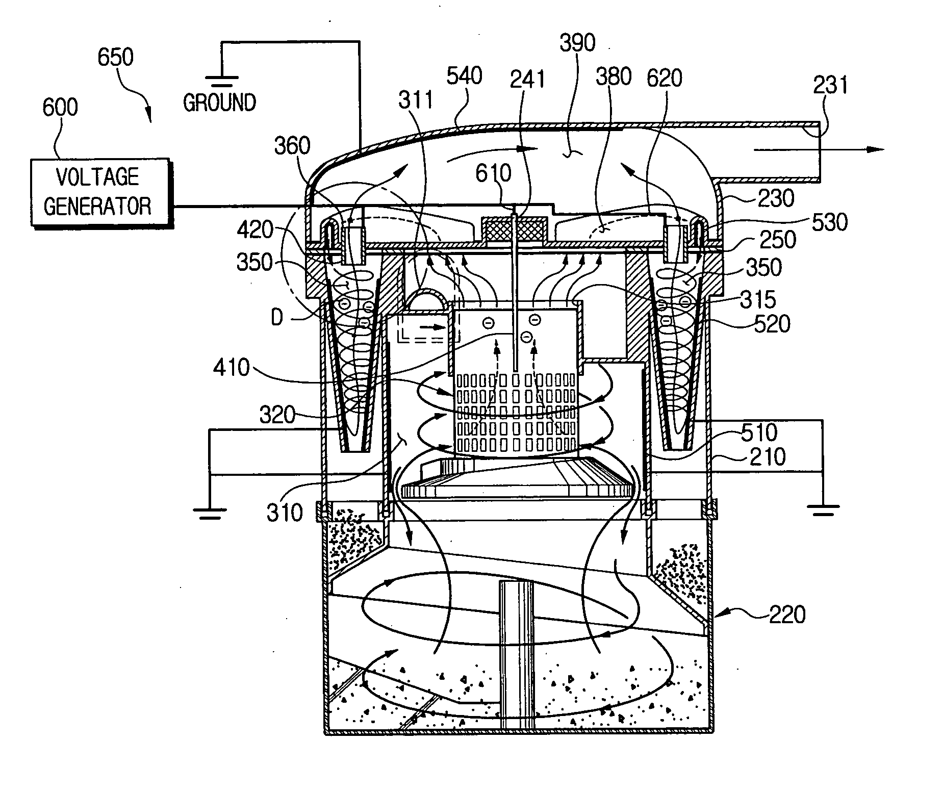
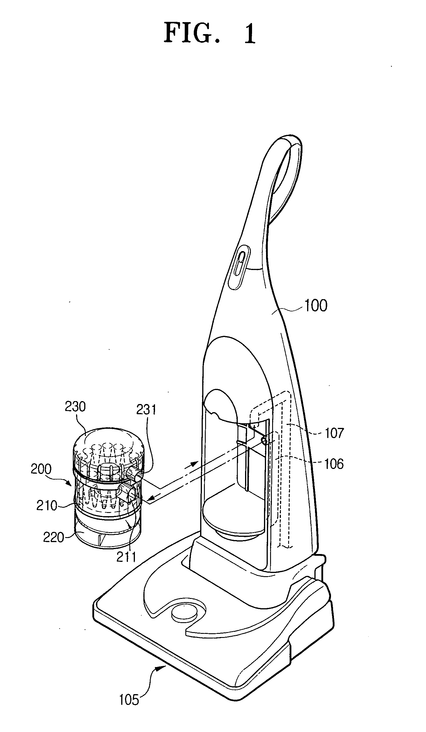
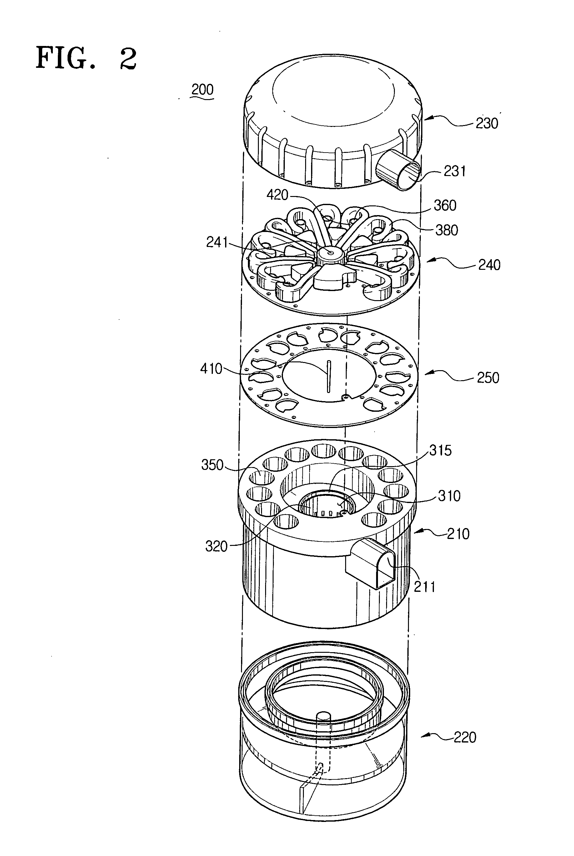
[0027] Referring to FIGS. 1 and 2, a dust collecting device 200 according to the first embodiment of the present invention is mounted into a cleaner body 100 to connect with an air suction duct 106 and an air discharge duct 107. As air is drawn in via a suction assembly 105, the air flows first through the air suction duct 106 and then through an air inlet pipe 211, and into the cyclone dust collecting device 200. The cyclone dust collecting device 200 separates contaminants from the air and discharges the air from an air outlet 231 to the air discharge duct 107 and to the outside of the cleaner body 100.

[0028] The cycl...


PUM


Abstract

A cyclone dust collecting device using a corona discharge is provided. The cyclone dust collecting device includes a cyclone chamber rotating air drawn in from the outside to separate contaminants from the air, a discharge pipe guiding the air separated from the contaminants to the outside of the cyclone chamber and including a discharge electrode part with at least a part made of a conductive material and a power supply unit supplying a power to the discharge electrode part for the discharge electrode part to perform a corona discharge.

Description

CROSS-REFERENCE TO RELATED APPLICATIONS [0001] This application claims the benefit under 35 U.S.C. § 119 (a) of Korean Patent Application No. 2005-50897 filed on Jun. 14, 2005, the entire content of which is incorporated herein by reference. BACKGROUND OF THE INVENTION [0002] 1. Field of the Invention[0003] The present invention relates to a vacuum cleaner. More particularly, the present invention relates to a cyclone dust collecting device for a vacuum cleaner, which separates contaminant from drawn-in air by using a cyclone dust collecting system. [0004] 2. Description of the Related Art [0005] When a suction motor is driven, a vacuum cleaner draws in contaminant-laden air via a suction assembly from a surface and separates contaminants from the drawn-in air so as to clean the surface. To separate the contaminants, a dust collecting device is employed. Recently, a cyclone dust collecting device has been popularized which separates contaminants from drawn-in air by using a centrifu...

Claims


Application Information

Patent Timeline
Patent Type & Authority Applications(United States)
IPC IPC(8): B03C3/36
CPCA47L9/1625A47L9/1641B04C2009/001B04C5/13B04C9/00A47L9/1658Y10S55/03A47L9/16A47L9/10
Inventor HAN, JUNG-GYUNOH, JANG-KEUNKIM, MIN-HA
Owner SAMSUNG GWANGJU ELECTRONICS CO LTD
Why Eureka
Try Eureka