Vehicle control system with slow-in-turn capabilities and related method

Inactive Publication Date: 2006-12-14
BONEAL
View PDF10 Cites 32 Cited by
  • Summary
  • Abstract
  • Description
  • Claims
  • Application Information

AI Technical Summary

Benefits of technology

[0022] In one embodiment, the steering device includes a steering wheel connected to a shaft carrying a third pinion adapted for engaging a first end of the first rack, whereby the movement of the third pinion created by the rotation of the steering wheel and shaft causes the first rack to move to and fro in the first direction. In this embodiment, the first rack is held in engagement with the first pinion by a roller bearing, and the second rack is a bar held in engagement with the second pinion by a pair of brackets. The brackets may include bushings for slidably engaging and allowing the bar to move to and fro in the second direction. The first and second planes in which the first and second racks move may also be generally horizon

Problems solved by technology

While this type of steering system generally provides an acceptable level of steer wheel traction and dynamic stability during regular turning at low speeds, problems occur during relatively sharp turns if the vehicle speed is relatively high and left unchecked.
For example, in the case of a self-propelled lawn mower, it is difficult if not impossible at high speeds to make the tight turn necessary to mow around a small round or circular object, such as a pole or shrub, without the operator actively reducing the vehicle speed.
Even at moderate speeds, a sudden, sharp turn may also result in a lifting of the wheels from the ground and a concomitant loss of traction.
This is deleterious, in that it allows the vehicle to essentially slide out of the turn and effectively miss the intended path of travel, which can not only be frustrating, but may also damage the turf.
The lifti

Method used


Image

  • Vehicle control system with slow-in-turn capabilities and related method
  • Vehicle control system with slow-in-turn capabilities and related method
  • Vehicle control system with slow-in-turn capabilities and related method

Examples


Embodiment Construction

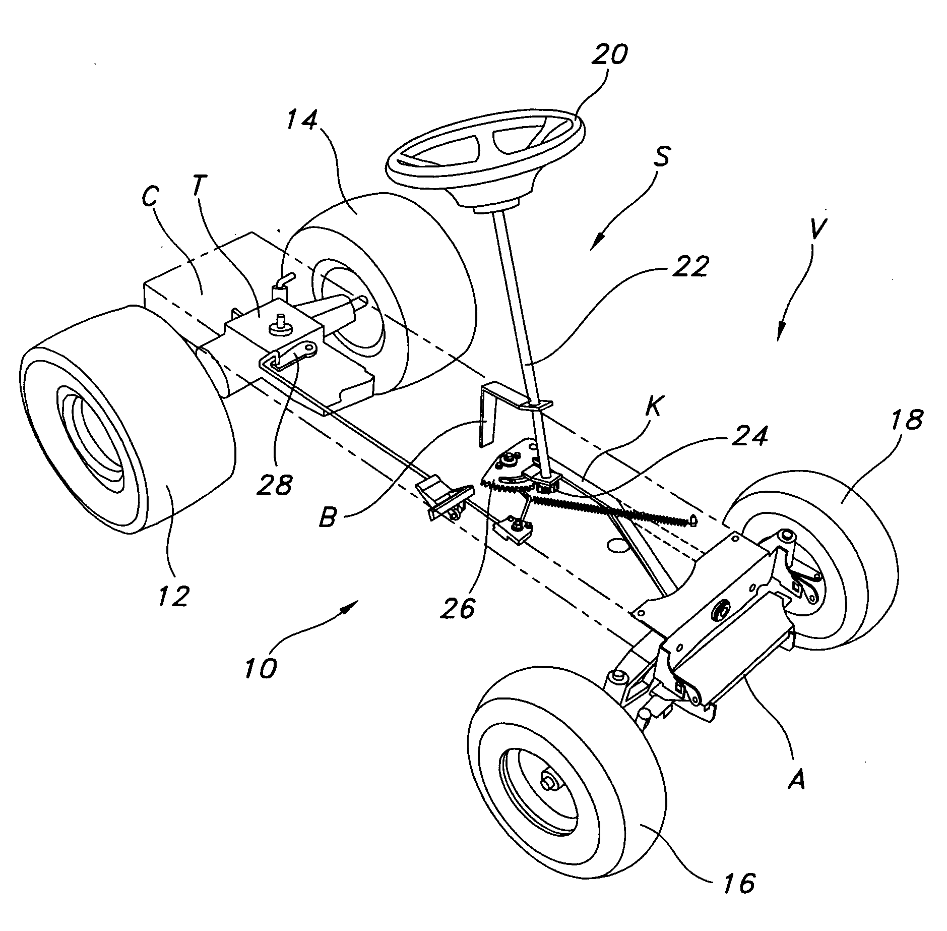
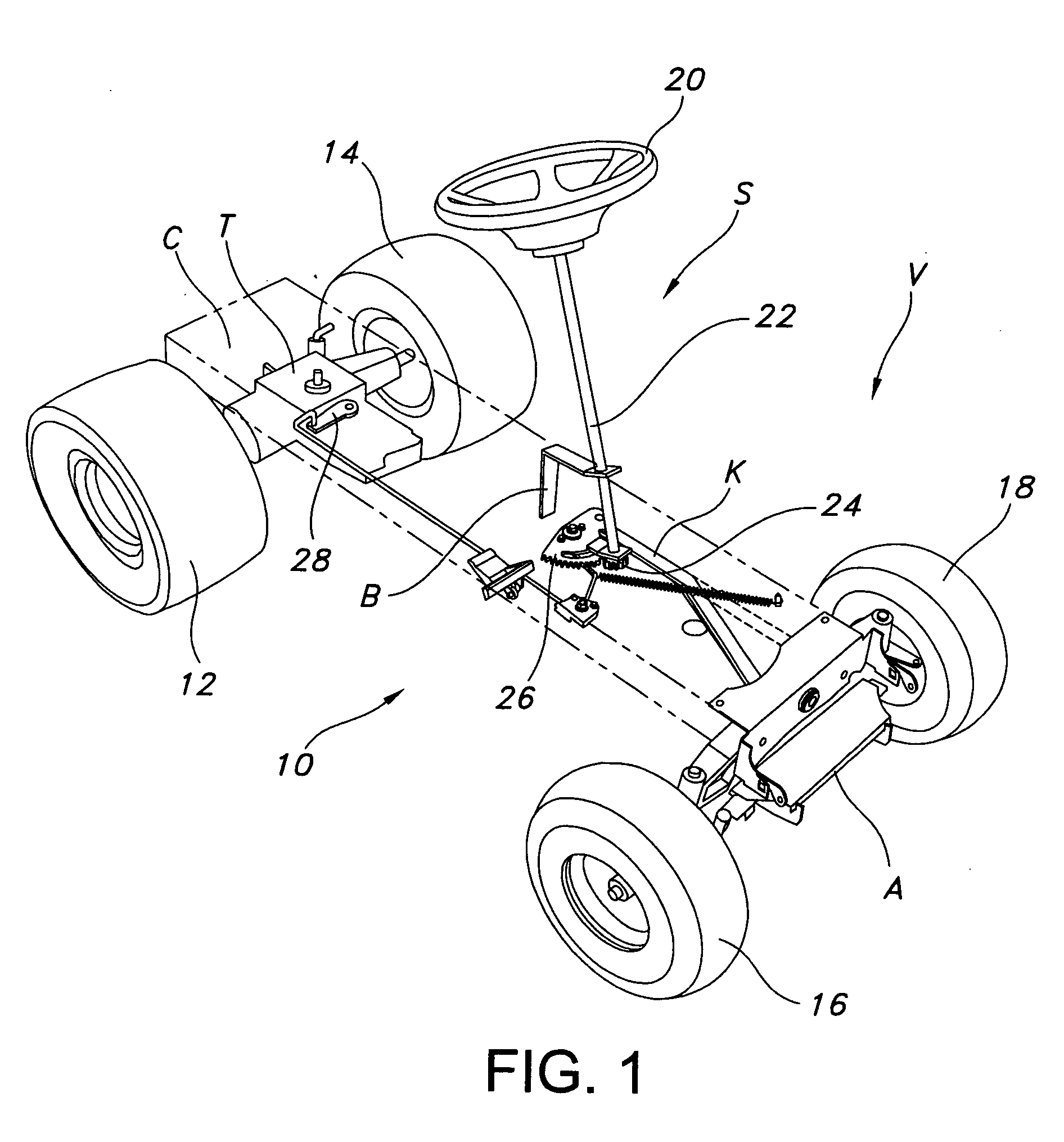
[0042] Reference is now made to FIG. 1 of the drawings, which depicts a vehicle V including the control system 10 with slow-in-turn capabilities forming one aspect of the present invention. The vehicle V is of the self-propelled type and, hence, includes a motive device for driving at least one ground-engaging structure, such as a wheel. In the illustrated embodiment, the motive device comprises an onboard transmission T for driving a pair of wheels 12, 14 mounted at the rear end of the frame forming part of the chassis C of the vehicle V at a selected speed and in a selected direction. The transmission T may be of the hydrostatic variety having three distinct operating modes (forward, reverse, and neutral) with variable speed control in at least the mode corresponding to forward travel. Alternatively, as discussed further below, the transmission may be of the belt-driven mechanical variety, including one with a forward drive mode having a plurality of different speeds (e.g., a five...


PUM


Abstract

A control system with slow-in-turn capabilities for use with a self-propelled, steerable vehicle, such as a lawn mower, is disclosed. In one embodiment, the system slows the vehicle speed when turns are made beyond a predetermined range and the speed is at or above a predetermined level, as determined by a speed control device operatively connected to the speed control structure of a motive device by a speed control linkage. This slowing results in increased traction for achieving tighter turns and also improves dynamic stability. Two different types of rack-and-pinion steering systems capable of being used with the control system are also disclosed.

Description

[0001] This application claims the benefit of U.S. Provisional Patent Application Ser. No. 60 / 359,387, filed Feb. 25, 2002, U.S. Provisional Patent Application Ser. No. 60 / 390,266, filed Jun. 20, 2002, and U.S. Provisional Patent Application Ser. No. 60 / 398,155, filed Jul. 24, 2002, the disclosures of which are incorporated herein by reference.TECHNICAL FIELD [0002] The present invention relates generally to vehicles and, more particularly, to providing a self-propelled, steerable vehicle with slow-in-turn capabilities. BACKGROUND OF THE INVENTION [0003] Vehicles in the form of riding mowers and tractors having a traditional mechanical steering system with a steering wheel controlled by a seated operator are in widespread use. While this type of steering system generally provides an acceptable level of steer wheel traction and dynamic stability during regular turning at low speeds, problems occur during relatively sharp turns if the vehicle speed is relatively high and left unchecke...

Claims


Application Information

Patent Timeline
IPC IPC(8): B62D11/24
CPCB60W30/02B60W30/14B60W30/18172B62D7/08B60Y2200/223B62D3/12B60Y2200/114B60W2540/18
Inventor OXLEY, LONNIE R.ARNOLD, JEFF K.
Owner BONEAL
Why Eureka
Try Eureka