Robot controller

a robot controller and controller technology, applied in the field of robot controllers, can solve the problems of reducing the upper limit of operation frequency, reducing the load on the bus, and preventing the robot from achieving high-speed performance, and achieve the effect of high speed and preventing the operation of controlling the robo

Inactive Publication Date: 2006-12-14
FANUC LTD
View PDF4 Cites 66 Cited by
  • Summary
  • Abstract
  • Description
  • Claims
  • Application Information

AI Technical Summary

Benefits of technology

[0018] It is an object of the present invention to provide a robot controller capable of transferring the environmental condition data picked up by detection means to a memory at high speeds without hindering the operation for controlling the robot.

Problems solved by technology

An increase in the number of devices connected to the first data bus 37 results in an increase in the load on the bus, lowering the upper limit of operation frequency and depriving the bus of high-speed performance.
However, provision of the robot controller 20 with the image-processing unit 22 separately from the robot control unit 21 is accompanied by the problem of an increase in the cost of the robot controller 20.
Therefore, the load on the bus increases, making it difficult to increase the transfer rate of the bus.
In addition, large amounts of image data are transferred through the same bus as that of the robot control data, which hinders the transfer of data for controlling the robot.
As described above, the conventional example (FIG. 4) is capable of processing images without imposing a burden on the robot control processor, but is provided with a processor for processing images separately from the robot control processor, raising the problem of increased cost of the robot controller as a whole.
According to another conventional example (FIG. 5), an image-processing function is incorporated in the robot controller at a lower cost than that of the constitution of FIG. 4, but the transfer of image data hinders the operation for controlling the robot.

Method used


Image

  • Robot controller
  • Robot controller
  • Robot controller

Examples


Embodiment Construction

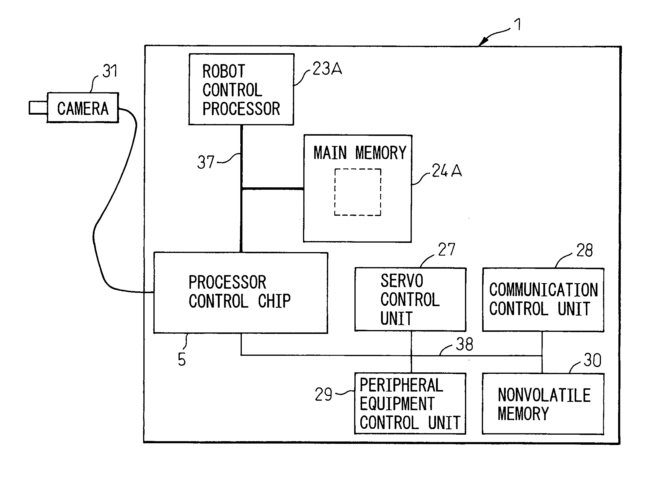
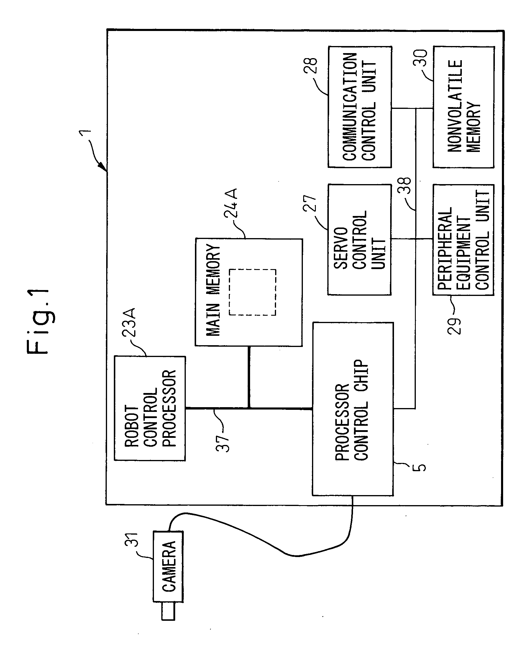
[0038]FIG. 1 is a block diagram illustrating an embodiment of a robot controller according to the present invention. The robot controller 1 includes a robot control processor 23A, a main memory 24A directly accessible by the robot control processor 23A, a high-speed CPU external bus (first data bus) 37 connected to the main memory 24A, a second data bus 38 having a transfer rate lower than that of the CPU external bus 37 and used for transferring the control data for controlling the robot, and a processor control chip 5 connected to the robot control processor 23A through the CPU external bus 37. A CCD camera 31 is connected to the processor control chip 5 to detect or recognize the environmental conditions for the robot. The environmental conditions for the robot represent a relative positional relationship between the robot and an object work before and after being clamped. The CCD camera 31 in this embodiment is used for detecting the position of the object work before being clam...


PUM


Abstract

A robot controller having a function for controlling the motion of a robot, comprising a processor for controlling the robot and for processing the environmental condition data representing the environmental conditions for the robot, a memory accessible by the processor, a writing unit for executing a function of writing the environmental condition into the memory, a first data bus connected to the memory, and a second data bus having a transfer rate lower than that of the first data bus and for transferring the control data used for controlling the robot, wherein the writing unit writes the environmental condition data into the memory through the first data bus, not through the second data bus. The writing unit can be a processor control chip which is connected to the processor through the first data bus.

Description

BACKGROUND OF THE INVENTION [0001] 1. Field of the Invention [0002] The present invention relates to a robot controller having a function for controlling the motion of a robot by processing data picked up by detection means such as a camera or a force sensor that detects the environmental conditions for the robot. [0003] 2. Description of the Related Art [0004] There has heretofore been known a robot controller incorporating an image-processing function as the robot controller having a function for correcting the motion of the robot that is taught by processing environmental condition data that represents the environmental conditions for the robot. [0005]FIG. 4 illustrates a conventional robot controller incorporating an image-processing function. The robot controller 20 includes a robot control unit 21 and an image-processing unit 22. The robot control unit 21 includes a robot control processor 23 for controlling the position / attitude of a robot, and which is not shown, a main memo...

Claims


Application Information

Patent Timeline
Patent Type & Authority Applications(United States)
IPC IPC(8): B25J5/00
CPCB25J9/161G05B19/042G05B2219/37563G05B2219/33162G05B2219/34012G05B2219/33157
Inventor HASHIMOTO, YOSHIKIKUBO, YOSHIYUKISERA, TAKEHISA
Owner FANUC LTD
Why Eureka
Try Eureka