Light-emitting device, driving method thereof, and electronic apparatus

Inactive Publication Date: 2006-12-14
SEIKO EPSON CORP
View PDF13 Cites 84 Cited by
  • Summary
  • Abstract
  • Description
  • Claims
  • Application Information

AI Technical Summary

Benefits of technology

[0007] According to an aspect of the invention, there is provided a light-emitting device comprising: a display unit in which a plurality of pixel circuits for allowing light-emitting elements to emit light with brightness corresponding to a data signal is arranged; an image acquiring unit (for example, image processing unit 10 in embodiments of the invention) for acquiring a first image and a second image corresponding to times different from each other in a frame period of time, respectively; a data-line driving unit for supplying a data signal corresponding to the first image to the pixel circuits belonging to a first group among the plurality of pixel circuits and supplying a data signal corresponding to the second image to the pixel circuits belonging to a second group other than the first group; and a light-emission control unit for allowing the light-emitting elements of the pixel circuits belonging to the first group to emit light in a first period of the frame period of time and allowing the light-emitting elements of the pixel circuits belonging to the second group to emit light in a second period other than the first period of the frame period of time.
[0008] According to the configuration, paying attention to an area including the pixel circuits of the first group and the pixel circuits of the second group, the substantial cycle of light emission of the light-emitting elements is elongated in comparison with the configuration that the light-emitting elements emit light and extinguish light every frame period without partitioning into the first period and the second period. Accordingly, it is possible to suppress the flickers. In addition, the images displayed in the first period and the second period are images corresponding to the times different from each other in a frame period. Accordingly, it is possible to suppress the image blur in comparison with the configuration that the image displayed on the display unit is maintained for the frame period.
[0009] In the invention, the total number of groups into which the display unit is partitioned is arbitrary. For example, in a configuration that a plurality of pixel circuits arranged on the display unit are partitioned into three or more groups, the images corresponding to the groups are acquired by the image acquiring unit, the pixel circuits of each group are supplied with the data signals of the image corresponding to the group, and the light-emitting elements of the pixel circuits of each group are allowed to emit light by the light-emission control unit in the periods determined by groups in a frame period. Such a configuration that the pixel circuits of the display unit are partitioned into three or more groups does not depart from the scope of the invention by assuming one group as the first group and another group as the second group, without paying attention to the other groups.
[0010] The distribution pattern of the pixel circuits belonging to the respective groups is arbitrary. However, in consideration of easiness in arrangement of the lines for driving the pixel circuits or in control of the pixel circuits, the configuration that the display unit is partitioned in a plurality of unit areas in which the arrangement of the pixel circuits included in the respective groups is common is more preferable than the configuration that a plurality of pixel circuits is irregularly partitioned into groups. For example, when the display unit has a configuration that a plurality of circuit groups, each of which include a predetermined number of pixel circuits arranged in a first direction, are arranged in a second direction intersecting the first direction (for example, when a plurality of rows, each of which includes a predetermined number of pixel circuits arranged in a

Problems solved by technology

However, a phenomenon called “flicker” that the whole brightness of an image is periodically var

Method used


Image

  • Light-emitting device, driving method thereof, and electronic apparatus
  • Light-emitting device, driving method thereof, and electronic apparatus
  • Light-emitting device, driving method thereof, and electronic apparatus

Examples


first embodiment

A: First Embodiment

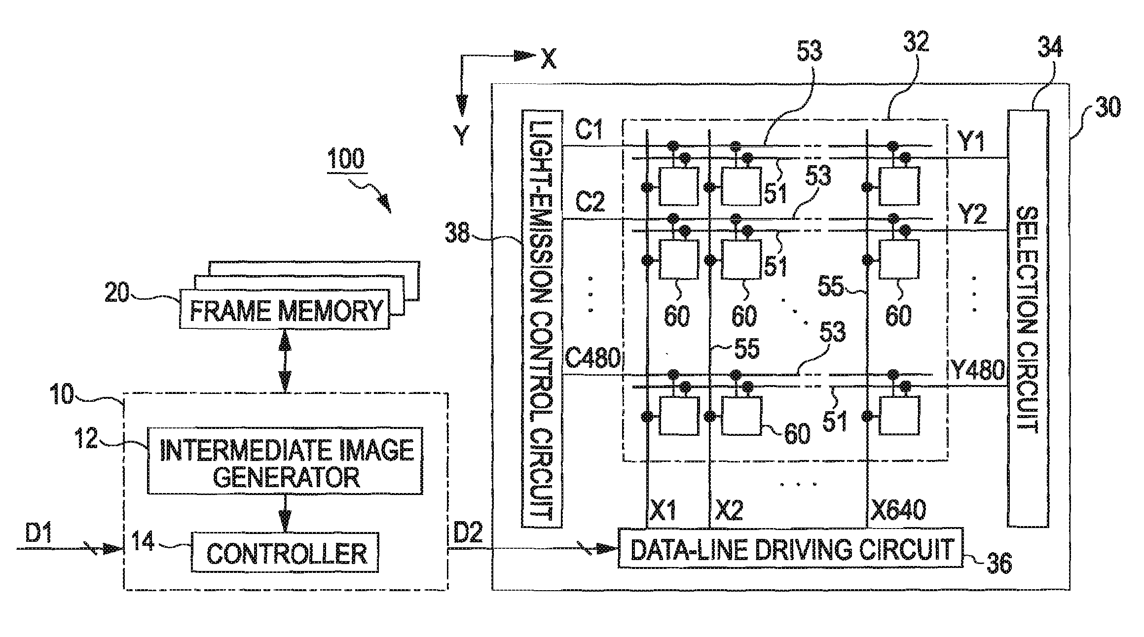
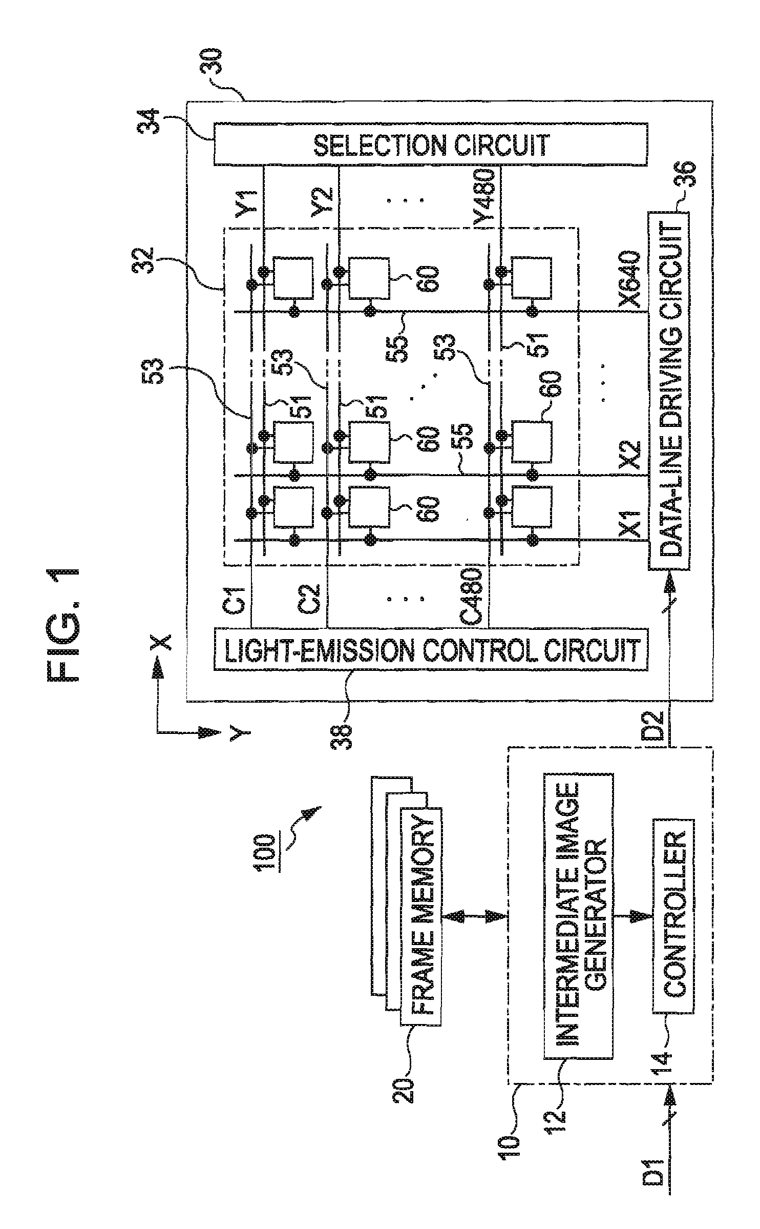
[0057]FIG. 1 is a block diagram illustrating a configuration of a light-emitting device according to a first embodiment of the present invention. As shown in FIG. 1, the light-emitting device 100 has an image processing unit 10, a frame memory 20, and a display panel 30. The image processing unit 10 serves to generate second image data D2 from first image data D1. The first image data D1 are digital data indicating details (colors and gray scales of pixels) of frame images constituting a moving image and are supplied from a generic unit such as a CPU of an electronic apparatus mounted with the light-emitting device 100. On the other hand, the second image data D2 are digital data indicating details of an image to be substantially displayed on the display panel 30. The configuration and operation of the image processing unit 10 will be described in detail later.

[0058] The display panel 30 serves to display an image on the basis of the second image data D2 and incl...

second embodiment

B: Second Embodiment

[0081] A second embodiment of the invention will be described below. In the second embodiment described below, the same elements as those of the first embodiment are denoted by the same reference numerals and description thereof will be properly omitted.

[0082] Such a configuration has been exemplified in the first embodiment that the pixel circuits 60 are partitioned into two groups of the odd-row group and the even-row group, the pixel circuits 60 in the odd-row group are allowed to emit light in the first period Pf1, and the pixel circuits 60 in the even-row group are allowed to emit light in the second period Pf2. However, the number of groups into which the display unit 32 is divided is not limited to it in the invention. In the second embodiment, it is exemplified that a plurality of pixel circuits 60 constituting a display unit 32 are partitioned into three groups.

[0083]FIG. 9 is a diagram illustrating a partition method into groups according to the secon...

third embodiment

C: Third Embodiment

[0089] A third embodiment of the invention will be described below. Although it has been exemplified in the first embodiment and the second embodiment that a plurality of pixel circuits 60 is partitioned into groups in a unit of row, the partitioning method into groups is not limited to it. FIG. 13 is a diagram illustrating a partitioning method into groups according to the third embodiment. In the figure, squares marked by “1” indicates pixel circuits 60 belonging to a first group and squares marked by “2”, indicates pixel circuits 60 belonging to a second group.

[0090] As shown in FIG. 13, in the third embodiment, a plurality of pixel circuits 60 is partitioned into the first group and the second group so that the pixel circuits 60 of the first group and the pixel circuits 60 of the second group are adjacent to each other in both the X axis direction and the Y axis direction (that is, so that the pixel circuits 60 of the second group are adjacent to a pixel circ...


PUM


Abstract

There are provided a light-emitting device and a driving method thereof capable of suppressing an image blur and a flicker. The light-emitting device includes: a display unit in which a plurality of pixel circuits for allowing light-emitting elements to emit light with brightness corresponding to a data signal is arranged; an image acquiring unit for acquiring a first image and a second image corresponding to times different from each other in a frame period of time, respectively; a data-line driving unit for supplying a data signal corresponding to the first image to the pixel circuits belonging to a first group among the plurality of pixel circuits and supplying a data signal corresponding to the second image to the pixel circuits belonging to a second group other than the first group; and a light-emission control unit for allowing the light-emitting elements of the pixel circuits belonging to the first group to emit light in a first period of the frame period of time and allowing the light-emitting elements of the pixel circuits belonging to the second group to emit light in a second period other than the first period of the frame period of time.

Description

BACKGROUND [0001] 1. Technical Field [0002] The present invention relates to a technology of controlling behaviors of light-emitting elements such as organic light emitting diodes (hereinafter, referred to as OLED). [0003] 2. Related Art [0004] There have been suggested light-emitting devices for displaying an image by controlling brightness of light-emitting elements arranged two-dimensionally. Among such light-emitting devices, a light-emitting device in which the light emission of the light-emitting elements is retained for the almost entire time length of a frame period is called a hold type light-emitting device. [0005] As disclosed in a non-patent document entitled “TIME RESPONSE OF DISPLAY AND IMPROVEMENT IN IMAGE QUALITY OF MOVING PICTURE”, IEICE Tech. Rep., ELD 2001-84, pp. 13-18 (2001-01), Kurita Soichiro / The Institute of Electronics, Information and Communication Engineers (see FIG. 3), in the hold-type display device, there occurs a phenomenon (hereinafter, referred to a...

Claims


Application Information

Patent Timeline
IPC IPC(8): G09G3/00
CPCG09G3/2025G09G3/22G09G3/325G09G2320/0261G09G2300/0861G09G2310/0218G09G2320/0247G09G2300/0842G09G3/12G09G3/20G09G3/30
Inventor IKEGAMI, TOMIO
Owner SEIKO EPSON CORP
Why Eureka
Try Eureka