
Method for calibrating flat panel display

a flat panel display and display technology, applied in the field of flat panel display calibration methods, can solve the problems of conventional calibration methods with a number of defects, color temperature errors, obvious side effects, etc., and achieve the effect of reducing timing costs and increasing the calibration ra

Inactive Publication Date: 2006-12-14
NOVATEK MICROELECTRONICS CORP
View PDF6 Cites 6 Cited by
  • Summary
  • Abstract
  • Description
  • Claims
  • Application Information

AI Technical Summary

Benefits of technology

[0009] Accordingly, at least one objective of the present invention is to provide a method for calibrating a flat panel display having the advantage of securing the measured data of multiple test patterns before analyzing the collection and adjusting all the parameters in a single operation. Hence, the calibration rate is increased and the timing cost is reduced.
[0010] At least a second objective of the present invention is to provide a method for calibrating a flat panel display capable of performing multiple measurements on the same test pattern and analyzing the collected data to reduce possible errors.
[0011] At least a third objective of the present invention is to provide a method for calibrating a flat panel display having the advantage of providing a delay period before displaying the test pattern and before obtaining the measured data. Hence, any transient instability in the flat panel display and the measuring optical meter is damped down to prevent possible errors.
[0017] In the preferred embodiment of the present invention, the method for calibrating a flat panel display includes performing a multiple of measurements on the same test pattern and analyzing the collected data to reduce errors. In addition, the present invention also opts for measuring and collecting the data of a multiple of test patterns before performing an analysis collectively to adjust all parameters in a single operation. Since there is no need for repeated analysis and adjustment, the calibration process is speeded up and the time cost is reduced. Furthermore, the setting of a delay period before displaying the test pattern and before capturing the measured data to wait out the transient fluctuation in the flat panel display and the optical meter results in less errors due to possible instability in the flat panel display and the optical meter.

Problems solved by technology

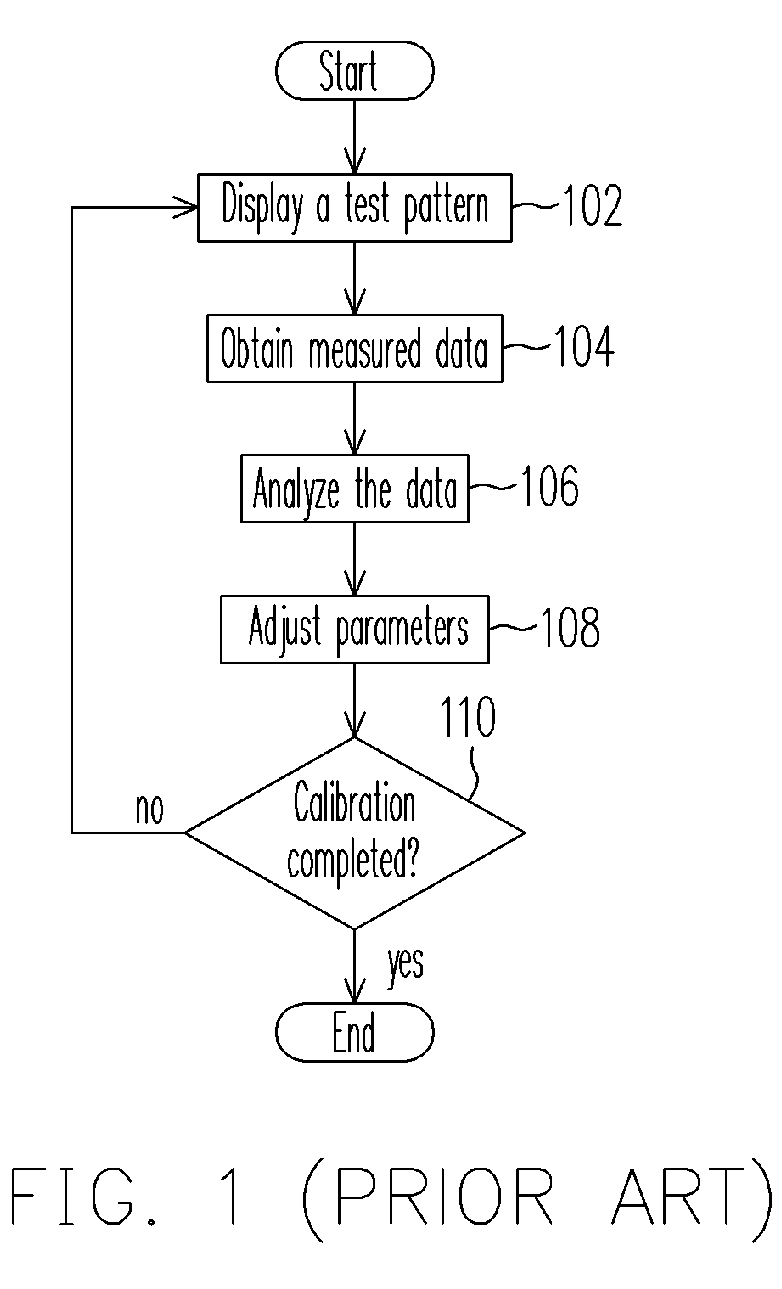
When the product is not calibrated or improperly calibrated, some obvious side effects will appear, which include color bias, color temperature error, low contrast and / or gray bias, for example.
The conventional calibration method has a number of defects.
Hence, the unstable transient states of the flat display and the optical meter can lead to errors.
Besides, if multiple types of test patterns or a multiple of measurements on the same pattern is required, the tedious procedure that includes displaying the test pattern, performing the measurement and analysis and adjusting the parameters has to be repeated many times. As a result, there is considerable waste of equipment and labor time.

Method used


Image

  • Method for calibrating flat panel display
  • Method for calibrating flat panel display
  • Method for calibrating flat panel display

Examples


Embodiment Construction

[0023] Reference will now be made in detail to the present preferred embodiments of the invention, examples of which are illustrated in the accompanying drawings. Wherever possible, the same reference numbers are used in the drawings and the description to refer to the same or like parts.

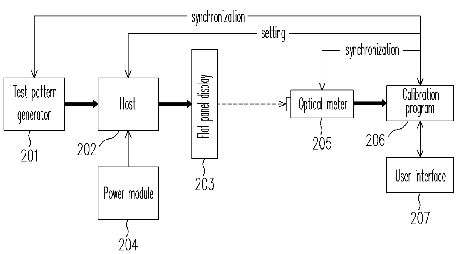
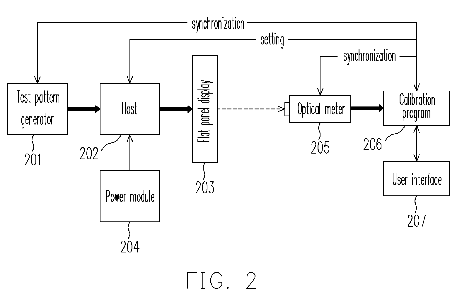
[0024]FIG. 2 is a hardware flowchart for showing the method of calibrating a flat panel display according to one embodiment of the present invention. In the present embodiment, a calibration program 206 receives instructions from an operator working through a user interface 207 so that the entire calibration process is under user control. First, a test pattern generator 201 generates a test pattern to a host 202. The host 202 receives power from a power module 204 and drives the flat panel display 203 to display the test pattern. Thereafter, an optical meter 205 measures the displayed test pattern on the flat panel display 203 and captures various data. Finally, the calibration program 204 collects...


PUM


Abstract

A method for calibrating a flat panel display comprising the following steps is provided. First, initialize a flat panel display and an optical meter. Provide a predetermined period of delay. Use the flat panel display to display a test pattern. Provide another predetermined period of delay. Use the optical meter to get measured data from the test pattern repeatedly until enough data for analysis is gathered. Repeat the step of displaying the test patterns until all test patterns have been displayed. Finally, analyze all the measured data to calculate the correct parameters for the control circuit of the flat panel display and set the parameters of the control circuit to the correct values.

Description

CROSS-REFERENCE TO RELATED APPLICATION [0001] This application claims the priority benefit of Taiwan application serial no. 94119460, filed on Jun. 13, 2005. All disclosure of the Taiwan application is incorporated herein by reference. BACKGROUND OF THE INVENTION [0002] 1. Field of the Invention [0003] The present invention relates to a method for calibrating a flat panel display. More particularly, the present invention relates to a method for calibrating and setting the control circuit parameters of a flat panel display. [0004] A flat panel display including the thin film transistor liquid crystal [0005] 2. Description of the Related Art [0006] Display (TFT LCD) is built using a number of optical, chemical and circuit components. There are quite a number of factors that affects the display characteristics such as brightness and color. For example, factors that affect a controller circuit include the video decoder, the de-interlacing circuit and the noise filter. Factors that affec...

Claims


Application Information

Patent Timeline
IPC IPC(8): G09G5/00
CPCG09G2320/0693G09G3/2092
Inventor SHEN, YU-CHUANHUANG, WEI-CHE
Owner NOVATEK MICROELECTRONICS CORP
Learn More